Morgan McMahon and Radar
Copyright Volume 2 SMEC Vintage Electrics
1989-1990 (now SMECC 2001)

Morgan McMahon joined the U.S. Navy in November, 1942. He attended naval electronics schools at Oklahoma A&M, Treasure Island and MIT’s Radiation Laboratory. He was assigned to teach loran at Pearl Harbor, but talked his way onto a destroyer, the U.S.S. Stephen Potter, DD-538. He was responsible for all electronic equipment aboard the ship from April 1944 until the ship was decommissioned in January 1946. The Potter participated in all major operations of the Third and Fifth Fleets in the Asiatic Theater of war. Mr. McMahon was particularly interested in optimizing the ship’s then-primitive radar countermeasures equipment, and was commended by Commander, Destroyers, Pacific Fleet, for "making more effective important equipment in daily use against the enemy". After the war, Mr. McMahon went on to U.C. Berkeley and a career in solid-state electronics. He also wrote and edited the Vintage Radio book series.
Presented here is an informative article on radar, actually done by one of the people who saw it from a 'users point of view'. What Morgan depicts here is a mix of background on the technology, theory, and personal experience.
-Edward A. Sharpe -editor
INTRODUCTION
The art and science of electronics went through its wild adolescence during World War II. This process was led by the new miracle tool - - - RADAR.
RADAR! The word rolls on your tongue. It smacks of new worlds, of futuristic adventure! The truth is that radar is even bigger than life. Even though the concept was simple, its execution was beyond the imagination or capacity of any one man. Many diverse disciplines finally fell into place, combined like Tinker Toys to produce radar. World War II, with radar, produced the mosaic of technology that became the electronics industry.
Development of radar showed that necessity is indeed the mother of invention. It showed that, in technology as on the battlefield, the real heroes do come through under pressure. Scientists and engineers proved that magnetrons, klystrons, T-R boxes, semiconductor detectors and other missing pieces could be invented, refined and produced on unbelievably short time schedules.
Radar (radio detection and ranging) lifted the veil of darkness. It accurately detected and followed movements of enemy ships and planes at night, in bad weather, and far beyond the range of optical devices. It controlled guns, torpedoes and bombing runs with great accuracy under all weather conditions. It allowed ground stations to guide interceptor planes to within kill range of enemy aircraft, and closed the interception by orchestrating the coup de grace. Radar provided precise navigation for war machines, and kept ship formations intact through all weather conditions. It told us which targets were friends and which were foes. It was a superb tool whose time had come, and which would become a most important aid in peacetime skies and on peacetime seas.
Radar was a key factor in winning World War II for the allies. It tilted many battles in our favor. It greatly magnified the effectiveness of our weaponry: In the battle of Britain it made a thousand planes, guided as interceptors, as valuable as ten thousand planes in the patrol mode of earlier days. Gun-control radars knocked down a major fraction of Germany’s buzz bombs before they could strike defenseless cities. Precision radar bombing knocked out critical enemy war machine manufacturing plants.
Please note that this article carries radar only to its accomplishments as of the end of World War II in 1945. There have been two generations of people and many generations of improved radar systems since that time.
THE RADAR SYSTEM
How does radar work? It sends out pulses of radio energy which reflects from any object that they hit. The direction that the echoes come from shows the compass bearing (azimuth) of the target. The time it takes for the radio pulse to reach the target and return as an echo shows the distance (range) of the target, at 12.4 millionths of a second for each mile of range. Elevation angle of the target can be used to calculate its altitude. Figure 1 shows how a radar set detects a target and displays the target "pip" on an indicator video-scope. This radarscope sweeps in time, but is calibrated in distance.
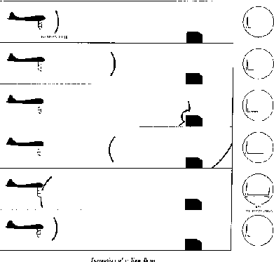
Figure 1: Pulse leaves antenna, reflects, and echo comes back. Radarscope shows return pip. Photo: Radar System Fundamentals.
Figure 2 shows how a "single-lobe" directional antenna determines target azimuth by rotating for maximum echo signal. In the illustration the antenna is at the left, and the balloon-like line shows sensitivity versus direction, the "antenna pattern". For precision azimuth, as in gunfire control, a double-lobe pattern (figure 3) can give great directional precision by finding the direction in which the echo "pips" for both lobes are of equal heights. This is called "lobing". The same trick can be used to find the elevation angle of a target.
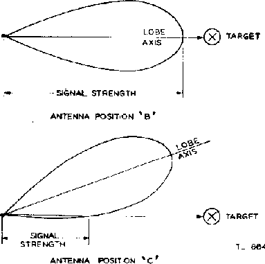
Figure 2: Single-lobe antenna pattern, for search. The target echo is strongest on the lobe axis. Photo: Radar System Fundamentals.
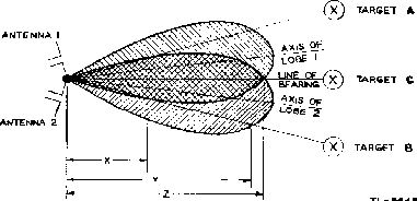
Figure 3: Double-lobe antenna pattern, for precise tracking.Equal echo strengths show exact bearing (target C). Photo: Radar System Fundamentals.
THE RADAR SET
Physically, the radar set is a group of metal boxes full of advanced circuitry, plus an indicator unit that displays the radar picture, Plus an antenna that usually revolves or scans in some manner.
Figure 4 shows the functional blocks of a typical radar set. These blocks may or may not correspond to the actual boxes in the radar. Usually, the operating controls are mounted on the indicator unit. The "main frame" unit on board ships contains the timer, transmitter, receiver, power supply and transmit-receive "duplexer" function of the antenna system. On the other hand, aircraft radar can be peppered amongst a maze of boxes tucked throughout the airframe. -And there are any of a number of gradations between these two extremes. Generic functions are as follows, as described in Radar System Fundamentals, an excellent introductory book published by the Armed Services during World War II.
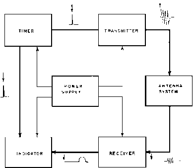
Figure 4: Basic functional blocks of a radar set. See the text for further explanition. Photo: Radar System fundamentals.
Timer: supplies the synchronizing signals which time the transmitted pulses and the indicator, and which coordinate other associated circuits.
Transmitter: Generates the radio-frequency (r-f) energy in the form of short, powerful pulses. Consists of the driver, modulator and r-f oscillator.
Antenna system: Takes r-f energy from the transmitter, radiates it in a highly directional beam, receives any returning echoes, and passes these echoes to the receiver. In single-antenna systems, it provides transmit-receive (T-R) switching of transmitted and echo energy. (Figures 5, 6 and 7 show often-used antenna structures.)
Receiver: Amplifies the weak r-f echo pulses returned by the target and reproduces them as video pulses to be applied to the indicator.
Indicator: Produces a visual indication of the echo pulses in a manner which furnishes the required information. Often integrated with the radar operating controls. (Figures 8 thru 11 show the most-used radar indicator oscilloscope presentations.)
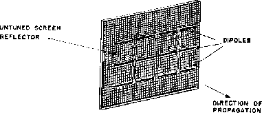
Figure 5: Stacked-dipole planar "bedspring" antenna. Photo: Radar System Fundamentals.
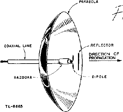
Figure 6: Dipole antenna with parabolic "dish", which focuses the Radar beam in the same way that a flashlight reflector focuses light. Photo: Radar System Fundamentals.
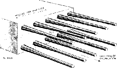
Figure 7: Phased-array antenna with plastic radiators. The radio waves propagate end-wise from the rods. This technique is called "end-fire." Photo: Radar System Fundamentals.
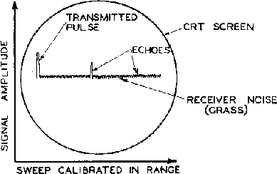
Figure 8: "A" scan for range measurement and target analysis. Photo: Radar System Fundamentals.
Figure 9: PPI scope for map-type display. Photo: Radar System Fundamentals.
Figure 10: "B" scan for interception and navigation. Photo: Radar System Fundamentals.
Figure 11: "C" scan for interception; Target "blooms" when it’s time to fire. Photo: Radar System Fundamentals.
USES OF RADAR
World War II radars had many jobs, which in turn demanded different system components. Makers of radars had to balance many different factors. What would the ideal system look like? What are the realities, such as available parts, time pressure, design skills, manufacturing capabilities, operating skills, weight, size, reliability, vulnerability, detectability, susceptibility to jamming, physical ruggedness and true performance in the operating environment? It is truly amazing that such good equipment was conceived, developed, manufactured and put into action on time schedules of months, not years.
In general, early-warning search radars demanded high pulse powers, efficient antenna systems, and very sensitive receiver systems. However, sharp target definition, exact bearing accuracy and precise range accuracy could be traded off to some degree for early detection capabilities. Practically, best early-warning frequencies ranged from below 100 MHz for long-range air search systems to 10,000 MHz for surface search. Higher frequencies gave better capture of small targets such as submarine periscopes.
Airborne radars were useful at frequencies as low as 144 MHz for search and attacks on surface ships. However, lower-frequency antenna systems were large and awkward for aircraft, with high wind drag. Development of the Magnetron resulted in vastly superior airborne radars at 3,000 and 10,000 MHz, which a much better performance to weight ratio and smaller antenna size. These sets were specialized for tasks such as long range search, interception, navigation and precision bombing. Some sets, such as the AN/APS-3, were competent for many roles. In particular, higher frequency meant greater precision and target "picture" definition.
TECHNOLOGY
There was an intense chickens-and-eggs spiral of systems ideas, technology and new perceived needs. For instance, it was apparent that new microwave pulse requirements were needed, bringing about the invention of the multi-cavity Magnetron, which in turn required new duplexers and receivers, which then made even higher-frequency magnetrons desirable round and round it went, to the benefit of all radar uses.
Important innovations included the Magnetron pulse generator, the klystron local oscillator, planar tubes (e.g. "lighthouse" tube), and semiconductor microwave mixer diodes - The list goes on and on. Incidentally, intense work on microwave semiconductor devices spawned the new generation of solid-state scientists who later started the semiconductor revolution, which in turn provided a hardware basis for the computer revolution.
U.S. NAVAL RADAR DEVELOPMENT
Early Naval radar research and development were conducted in the mid-to-latter 1930’s by the Naval Research Laboratory. NRL moved into the 1940’s in conjunction with the Radiation Laboratory at MIT, and Bell Telephone Laboratories. Industrial laboratories, most notably RCA, lent early support.
NRL’s early radar work resulted in a successful radar test aboard the destroyer U.S.S. Leary in 1937. Following the "breadboard" test, a more formalized prototype, called the XAF, was installed on the battleship U.S.S. New York in December, 1938. This 200 megahertz (MHz) frequency set produced 15 kilowatt (KW) pulses, each 5 microseconds (usec) wide. It had a large planar antenna, dubbed the "flying mattress". Performance was so good that 20 more sets, called CXAM, were built and put into service on battleships, cruisers, aircraft carriers and a seaplane tender. Very successful as search radars, these sets were used through the entire war.
XAF-derived Navy programs moved on to 200 MHz air search prototypes with 330 KW pulse outputs, very sensitive receivers and planar "bedspring" antennas. They picked up aircraft up to ranges of 150 miles, previously unheard-of. Production models of this set were the SC and SK made by General Electric, and the SA made by RCA. SC was made for destroyers; SK was the same set with twice-as large antenna, for cruisers, battleships and aircraft carriers. Some later SK’s were provided with large dish-type antennas. SA was used on escort ships such as destroyer escorts. Note also that these radar sets were used on ships of our allies
.
Higher-frequency XAF descendants, 400 to 600 MHz, were produced, the prime example being the SR series.
Another descendant of Navy’s XAF "breadboard" was the XAS aircraft-warning radar for submarines. Tested aboard the U.S.S. Gar in June 1941, it became the SD, the submariner’s air-search workhorse radar. It operated at 114 MHz, with 140 KW output pulses.
THE MAGNETRON
The high-powered magnetron ("Maggie") was the greatest new device to impact radar in World War II. It allowed radar to move up to microwave frequencies with high pulse power. This showed an order-of-magnitude improvement in combinations of target definition (sharpness), precision of location, range precision, smaller size and/or higher-performance antennas, and better detection of targets in sea or ground "clutter" echoes. Shorter pulses, on the order of tenths of microseconds, permitted minimum target ranges of hundreds of yards, rather than halves of miles, permitting full radar control of interceptor aircraft guns. Cumbersome antennas were scaled down to miniatures that could be carried in airplane wings or bomb-size wing pods.
In September, 1940 Sir Henry Tizard’s mission from Great Britain brought a magnetron to the U.S. This was part of a mutual "show and tell" aimed at combining Allied electronic technologies to beat the Axis Powers. The sample magnetron was a 3,000 MHz microwave device putting out pulse power of 10 KW. In order to take the shortest path, it was decided that the U.S. would copy the British magnetron, adjust its design as necessary, and jump into manufacture of this remarkable tube. The most bothersome problem was to keep the tube from "moding", which was a bad habit of jumping into spurious oscillation at unintended frequencies. Then the British invented "strapping", a technique of tying alternate teeth of the magnetron together, constraining it to be stable. The result was a 3,000 MHz device putting out 50 KW pulse power, eminently capable of powering a microwave radar.
Magnetrons had been known since 1921. However, the multi-cavity, high-power magnetron was invented in 1939 by Randall and Boot in Great Britain. Held as a tight secret, it was divulged to U.S. engineers by the Tizard Mission. Picked up immediately, it was put into production within months. The Naval Research Laboratory (NRL), The Radiation Laboratory at MIT, and Bell Telephone laboratories were the chief U.S. participants in developing the American version of the magnetron and employing them in radar systems. Major microwave policy guidance was provided by the National Defense Research Committee-also known as the NDRC.
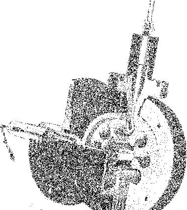
Figure 12: High-power multi-cavity magnetron (cutaway view). Photo: Radar System fundamentals.
The magnetron (Figure 12) is basically a large, elegant vacuum tube diode. The plate is a large copper ring. It has slots and cavities in it, that resonate (oscillate) at the desired microwave frequency. An extremely strong magnetic field is applied parallel to the axis of the electron-emitting cathode. When a voltage of about 20,000 volts is applied to the plate ring, electrons leave the cathode toward the plate. the magnetic field, however, makes the electrons travel in a curved path. When the anode voltage and magnetic field are just right, the electrons travel in synchronism with the resonant frequency, and energy is given to the electrons and transferred to the cavities. This microwave energy can be transferred (coupled) out by a loop in one of the cavities.
MICROWAVE SURFACE SEARCH RADARS
As soon as Bell Labs engineered a producible American magnetron, Western Electric set up to build them. NRL and the MIT Rad Lab developed a prototype 3,000 MHz surface search radar and tested it on the U.S. Semmes in the spring of 1941. They then worked closely with the Raytheon company to produce the first American microwave surface search radar, model SG. This radar produced 5OKW pulses, 1.3-2 usec wide, at 3,000 MHz. It was highly successful, with nearly 1,000 being manufactured in 1942-43. Many were still in operation some 20 years later. (The SG radar is described in some detail later in this paper.)
Other Navy 3,000 MHz radars quickly followed, including the SE, SF, SH, SJ, SL, SM, SN, SO, SP, SQ, and SV.
FIRE-CONTROL RADARS
Earlier work with the XAF showed great promise for gunfire control ("fire control") radars. They could work equally well in any weather and any time of day or night. Ranging accuracy could be almost exact, compared to the well-known inaccuracies of optical ranging; the first salvo of shells could bracket the enemy ship, rather than being "walked in".
NRL developed an accurate "range only" radar set, the CXAS-1, which became the FA, or Mark-1. The 500 MHz, 2 KW transmitter, using old-style vacuum tubes, was inadequate. Work was begun on the more powerful set, under the name FB, or Mark-2. Then the news of the wondrous Magnetron hit, with stories of 40 KW output at 700 MHz. FB was immediately dropped, and development started on the FC or Mark-3, magnetron-powered gun-laying radar. The prototype was installed on the U.S.S. Philadelphia in October, 1941, with great success. Immediate orders were placed for 125 production units, which were installed on capital warships.
Use of the F-series radar for anti-aircraft fire control was another obvious opportunity. What was most-needed was antenna lobing in the vertical direction for accurate elevation information. Development of the FD, or Mark-4, anti-aircraft radar was conducted along with the FC, and was tested aboard the destroyer U.S.S. Roe in September, 1941. Full production started by the end of 1941, and 375 units were delivered to the fleet. These sets saw heavy combat duty through the end of the war. (Mark-4 is discussed in some detail later in this article.)
FD’s only real problem was elevation inaccuracy at with low flying targets such as torpedo planes, due to radar reflections from the surface of the ocean. To correct this, the FM (Mark-12), was developed, with horizontal lobing only. It was co-mounted with the Mark-22, a 10,000 MHz elevation-finding radar with a nodding segment-shaped antenna. This combination was excellent, and 700 units were produced starting in 1943.
Mark-8, successor to Mark-3, was a highly accurate surface fire-control radar with 100 KW output at 3,000 MHz, using a phased array antenna (see Figure 7). Using a 3-high by 14-wide array of polystyrene rods, it had an extremely sharp, lobed beam. 179 Mark-8’s were built starting in 1942. Mark-8’s successor was Mark-14, with a horizontally-rocking antenna, operating at 8800 MHz. 107 Mark-14’s were built starting in 1945.
The aforementioned radars were used with heavy anti-aircraft guns from 5-inch, 38-caliber (16 feet long) on up in size. In addition, thousands of conical-scan antenna microwave radars were used with smaller guns such as the 40 millimeter bofors. These gun directors were usually mounted immediately adjacent to the individual gun batteries. These radars were magnetron-powered, operating at 3,000 or 9,000 MHz. FJ (Mark-9) and FL (Mark-10) were the first produced, followed by Mark-28, 29, 34, 35, 37 and 39, Plus AN/SPG 48, 49 and 50.
AIRBORNE RADAR
Some airborne radars operated as low as 144 MHz frequency during the war (Japanese Mark-VI). The British Air-to-Surface-Vessel radar ASV Mark II, at 176 MHz, saw extensive service against submarines and surface vessels, with good results. With major modifications, it became the British ASE and the U.S. SCR-521. The most significant improvement in the ASE was the use of an antenna duplexer (T-R box), which permitted the use of just one send-receive antenna, rather than two separate units. This yielded appreciable improvement in aircraft performance because of drastically reduced wind drag.
ASE’s successor was ASB, last of the non-magnetron Allied airborne sets. ASB’s performance made it the most-used aircraft radar of the war; 26,000 units were built. Output was 200 KW pulses, 2 usec pulse length, at 515 MHz. Each plane carried two directional Yagi antennas (looking something like a small TV antenna), one on each side. Pointed to the sides, the antennas were in a side-looking search mode. Pointed to the front, they performed forward search. In this mode, the antennas were pointed a few degrees apart, slightly wall-eyed. This way, the pilot could home in on his target by matching the sizes of echo pulses from the two antennas, sort of like "lobing" described earlier in this article. When the two echoes were equal, the plane was headed directly at its target.
Advent of the magnetron gave a major jump in aircraft radar effectiveness, since the microwave frequency (usually 3,000 or 10,000 MHz) allowed great reductions in system size and weight. Conversely, more "bells and whistles" could be added to the radar set without increasing system size. The Navy developed the 3,000 MHz ASG, which became the AN/APS-2, which could detect ships up to 60 miles. 5,000 of these air to surface radars were built and installed in large patrol and attack aircraft, including blimps. They were used to sink thousands of tons of enemy shipping and many submarines.
The following step, to 10,000 MHz frequency, allowed a 3-fold shrinking of antenna dimensions and substantial weight reduction compared to the AN/APS-2. This permitted mounting transmitter-receiver-antenna elements of the radar in small under-wing pods, or in fairings built beneath the plane’s wing. The Navy’s ASD radar, developed between MIT Rad Lab, NRL and Sperry, became the AN/APS-3 radar put into production by Philco in 1943. This radar could detect ships up to 300 miles away, and a surfaced submarine at 15 miles. It was used by medium-sized patrol planes and by attack planes such as the TBF torpedo-bomber. It was ideal for blind-bombing, and saw much service in the weather-bound arctic. A lighter version of the AN/APS-3 was the AN/APS-4, produced by Western Electric in 1944. AN/APS-4 was ideal for lighter carrier aircraft, ranging from TBM torpedo bombers to F6F night fighters. Missions included interception, bombing, torpedo runs and navigation. (The AN/APS-3 is covered in more detail later in this article.)
The AIA, another small-sized, high-performance radar, was developed for NRL by Sperry. This set was further developed and manufactured by Western Electric in 1944. This was the only full function single-engine night interceptor radar available in World War II.
ARMY AND AIR FORCE RADAR
Although radar was not crucial to conventional battlefield warfare, it became very important as enemy attack planes entered the picture. Also, the Air Force was part of the Army in the early days, first as part of the Signal Corps, then as the Army Air Corps, then as the Army Air Force (AAF), and finally the independent Air Force. Army radar development was led by the Signal Corps Laboratory in Fort Monmouth, New Jersey.
Army development of surface-to-air radars was intensive, both in early-warning and in gun control. The Army could take full advantage of existing technology, because space was no particular problem. Focus was on the 200 MHz frequency region, allowing very high pulse powers with conventional vacuum tubes. Also, large antenna arrays could be used in searching for distant aircraft. Navy surface-to-air systems, on the other hand, had both space and weight problems because they were on board ships.
Figure 13: SCR-268 air search radar, used through World War
II.
Photo: Radar Systems Engineering, Rad Lab Vol. 1, P204.
SCR-268 (Figure 13) and its cousin the SCR-270 were the first U.S. Army search radars manufactured and deployed. The prototype of SCR-268 was demonstrated in June, 1937. It replaced sound locators starting on 1938, and was further refined for searchlight and anti-aircraft gun direction in 1939. It produced 50 KW, 7-15 usec pulses at 200 MHz, at a pulse rate of 4098 pps. Angular (azimuth) and elevation accuracies were +/- 1 degree with lobing turned on. The left-hand antenna array in the photo is the transmitter, with a 4-by-4 array of dipoles. The inboard right-hand array is the azimuth antenna, a 6-by-4 dipole array, and the outboard right-hand array in the 2-by-6 dipole elevation antenna. Maximum design range was 40,000 yards.
Though primitive in appearance, SCR-268 was a major Army set through the end of World War II. It was "in all theaters of operation during World War II and was the backbone of the early warning systems installed along our coasts and insular possessions" according to the National Defense Research Committee’s final report on the war. It was also used by the British in defending the British Isles. It was the first radar to be coupled directly to gun-director computers, a major advancement of technology.
SCR-270 was an effective early-warning radar. Its prime claim to fame is that it was the first set to detect Japanese planes headed for Pearl Harbor on December 7, 1941. Unfortunately, the warning was ignored.
The advent of the magnetron microwave transmitter made possible another high-performance radar, the SCR-584. This 3,000 MHZ radar was highly portable in its trailer with a pop-up microwave dish antenna. It was very effective both in air search and in precision anti-aircraft gun control, an impossible feat with non-microwave sets. Radar experts have referred to SCR-584 as "the most widely used and generally successful of the resulting equipments" from the application of magnetrons to ground-based radars. It was heavily used in the defense of Britain, as well as by all U.S. ground forces. It is credited with knocking down a major fraction of all the German "buzz bombs" that crossed the English Channel. (SCR-584 is more fully described later in this article.)
Compared to surface-to-air radars, airborne radars had much more in common between the Army Air Force and the Navy. For instance, Air Force’s SCR-717 3,000 MHz radar, used for navigation and bombing, was very similar to Navy’s ASG (AN/APS-2), except that it had a B-scope presentation instead of Navy’s PPI scope.
As one might expect, inter-service rivalries and missing communications channels limited Army-Navy cooperation. The AN/ designator (for Army-Navy inter-service use) was more of a prayer than a reality.
Another example of commonality was the RAF’s Mark-IV aircraft intercept set. The AAF adopted a very similar set, the SCR-540. Both sets had the same trouble; the low operating frequency (200 MHz) gave very bad ground echo problems, so that the systems worked only at distances shorter that the airplane’s altitude. Then the cooperative shoe shifted to the other foot: Fort Monmouth developed an AAF microwave intercept set (SCR 720) that greatly reduced ground echoes and increased range by three times. The RAF adopted this new set also.
Another AAF radar set merits mention. This is the AN/APS-15, a 10,000 MHz precision bombing set with sector scan and PPI display. This set used a unique "cosecant squared" antenna that gave a true representation of the ground surface mapping, rather than a distorted slant-range picture. It’s things like this that made life better for bombardiers.
RADARS OF THE AXIS POWERS
We will not dwell on axis power radars in this article. However, Tables I and II later in this article show that both Germany and Japan employed the radar art. Their major disadvantage was that they didn’t have the magnetron, so they couldn’t go to microwave frequencies for superior performance. But, we did!
IFF EQUIPMENT
IFF (Identification Friend or Foe) equipment is necessary to make sure whether a blip on the radar screen is a friend or a "bogey". A bogey is a target that you must presume to be an enemy until you know better. This is critical to the health of all parties involved. Originally, each country developed its own IFF equipment. In 1940 the U.S. and Great Britain decided on a common IFF format so we wouldn’t be shooting at each other. Incidentally, the Germans had their own IFF equipment, but it was less sophisticated than ours.
The typical scenario is this: A shipboard radar operator on the destroyer DD-538 is watching his SC-2 PPI radarscope. He sees a new pip on the scope, closing fast. Is it a friend? An enemy attacker? He presses a key on his radar console, and his IFF interrogation equipment sends out a coded signal. If it’s a friend, the airborne IFF transponder sends back a coded response which shows up as a tail on the pip on the radarscope. If the pilot has turned on his transponder, and if he has cranked in the right code, he doesn’t get shot down.
RADAR COUNTERMEASURES (RCM)
Electronic countermeasures (ECM) is probably the most elegant, fascinating and secret "game" in military electronics. In World War II, this consisted mostly of radar countermeasures (RCM). It was heavily concerned with "jamming", "spoofing", and intercepting and analyzing the enemy’s radar signals. Jamming consisted of blinding the enemy radar so that it couldn’t detect, track, or attack the good guy (you).
One jamming technique was to blind the other’s radar receiver by transmitting noise, pulse bars ("railings") or other disruptive patterns. This would show on the PPI scope as a large pie-slice of wash-out. Sometimes an expert operator, watching his "A" scope, could discern some of the targets in this mess. This tool could be used by attacking planes, or by defending units. It could also be used in ship-to-ship engagements.
Another major airborne jamming tool was called "snow", "chaff" or "window". It consisted of millions of micro-thin slips of metal foil, cut in length to resonate at the frequency of the defending radar. The result was that the defending radar operator saw a large cloud of echoes on his radarscope, completely obscuring echoes from the attacking planes. Then attacking planes would pop out of this cloud, without leaving time for defensive radar action. Incidentally, this foil had a secondary offensive value; In Germany, thousands of cows ate the stuff and died.
Spoofing could be very elegant. For instance, one plane with a special transponder could send out a string of false echoes. This could make one red-herring plane look Like an entire formation of attackers. While defenders were occupied by intercepting this bogus "formation", other formations, flying low, could come in and decimate them.
Another trick was to activate German planes’ IFF transponders, then home in on them and shoot the planes down.
One major opportunity was to build missiles to home in on enemy radars, destroying them. This weaponry was not extensively deployed during World War II, but has been heavily used since then.
Bogus IFF transponder responses were tried by Japanese planes to penetrate aircraft carrier task forces. Signals were very ratty, and presumably didn’t fool anyone.
RCM receivers were very effective in detecting enemy radars at ranges far beyond the range of our own radars. This is because we could detect their strong transmitter pulses at ranges where echoes were too faint to be received. Good RCM operators could tell when snoopers were searching, when they had discovered us, and when they were commencing a run on us. RCM transmitters of fairly low power (10-100 watts) could thoroughly jam the enemy’s radar receiver, since echoes bounced off of us would have only milliwatts of power.
FIXED RADAR TRANSPONDERS
Radar transponders sent pulses back to interrogating radars, thus providing reference points for bombardments, landings and other offensive actions. The trick was to place these transponders at the right spots in enemy territory. Fortunately, they didn’t have to be placed directly at the target, even though that would be preferred. As long as they were planted at known locations, they established the map grid to be used by attacking forces.
The AN/APN-13 was widely used in assault landings by allied forces in the Pacific. Another fixed transponder was the YH. Later came the YJ for use with the ubiquitous ASB aircraft radar. Model YJ-2, and its successor AN/CPN-6, were used both for aircraft precision bombing and for homing back to the mother aircraft carriers. Type YL was an "on-course" beacon set up aboard a landing ship to guide landing craft to the right spot on the beach; some gutsy person would have previously planted a YN transponder on the beach as a target at which to direct the YL.
Fixed radar transponders were heavily used in navigation along coastlines. You could fly from San Diego to Attu Island without ever being out of touch with a transponder. They were also used in harbor channels for navigation at night and in fog.
ADVENTURES IN RADARLAND
World War II radars were fascinating to work with, both for operators and for technicians. Radar sets, being very complicated, would work fine for days, then suddenly behave like cranky camels. They would behave great during normal conditions, then might do strange things at the critical moment, when gunfire and concussion were shaking their innards. The radar operators had to be eternally observant, and also skilled in the vagaries of radar sets, propagation conditions, and enemy tactics.
Radar sets had their own personalities, as any technician would swear. A good radar technician was really worth his salt, keeping his pet radars in top shape and working through all the critical moments. He knew which set was going to do what under stress. He haunted the radar room during "general quarters" in order to move instantly as problems developed.
Radar technicians were also entrusted with operation of the "weird" hardware, such as radar countermeasures equipment. Some of my most fascinating moments were spent trying to outguess the guy at the other end.
"Personal experience" comments appearing in the following sections under "Specific Radar Equipments" are based on the author’s tenure in charge of the radars aboard the destroyer U.S.S. Stephen Potter (DD-538) through the heyday of the Third and Fifth Fleets. This included the Marshall Islands, New Guinea, Saipan, Tinian, Guam, Iwo Jima, the Philippines, China Sea, Okinawa, Formosa (now Taiwan), and Japan. Most interesting was being part of the "Bait Group" staked out to bring out the Imperial Japanese Navy in July, 1944. As one might surmise, radar was essential to our health and well-being through those days.
One radar technician (that was me) used to say "Do I know radars? Hell, I was married to three of them for almost two years!"
SPECIFIC RADAR EQUIPMENT
Generalities are fine, but one must look down the throats of a few sets in order to understand the creatures. The next five sections describe some significant radar sets and related equipment.
SC & SK SHIPBOARD RADARS
In 1938 the U.S. Navy developed its first operational air search radar, the XAF. It provided 15 kilowatts (KW), 5 microsecond (usec) radio-frequency pulses at 200 MHz. Its antenna structure was quite large, 20.5 by 23.5 feet, and was known as the "flying mattress". It was used on large ships through the war.
However, the Navy needed smaller radar sets with superior performance. NRL developed a new set, the XAR, with 22 times the pulse power and 11 times the receiver sensitivity of the XAF. These advancements were made possible mostly by the 127A ring oscillator transmitter tubes developed by Eitel-Mc Cullough (Eimac), and by the planar "lighthouse" tubes developed by General Electric. XAR was first demonstrated aboard the destroyer U.S.S. Semmes in July, 1941.
XAR was the prototype for the SC, SK and SA radars. SC and SK were identical except for antenna size, was larger for the SK. Transmitter power was 330 KW, pulse width 5 usec, and frequency in the 200 MHz band. Maximum aircraft target range was about 80 miles for the SC and 150 miles for the SK. Large numbers (over 1,000) of these sets were built in 1942-45. SC’s were destined for destroyers, and SK’s for larger ships. SA’s, not covered here, were used on smaller escort vessels.

Figure 14: SC-SK air search radar, first mass-produced Navy set. Photo: Evolution of Naval Radio-Electronics, Page 185.
Modules of the SC and SK radars are shown in Figure 14 (See also figure 4). The transmitter cabinet shown at the far left houses the ring oscillator transmitter employing four special Eimac type 127A tubes. The assembly that looks like an automobile muffler is the T-R "box" for automatically switching the antenna between transmitter and receiver. Interestingly, these T-R cavities employ old-fashioned spark gaps, complete with ozone smells and crackling sound tones. The main console has the receiver (with pre-amplifier on top), A-scope, and related controls on the left, antenna control module on the right, and a large, 15-inch diameter PPI scope in the lower unit. A variac and transformer, at far right, supply high voltage for the modulator. In SC and SK, the modulator runs from the 60 Hz power line, firing the transmitter at line-voltage peaks.
The SC antenna is of the planar "bedspring" type as shown in Figure 5. It is relatively long and narrow (5 by 15 feet, 2 dipoles by 6 dipoles) in order to have a fairly sharp horizontal antenna pattern. It also has 4 IFF antenna dipoles across the top of the bedspring. On destroyers the antenna is on the tip of the mainmast, 80 feet above the water. These antennas are more rugged than they appear, suffering damage only when doused into huge waves during typhoons, or in combat. The SK antenna is larger (15 by 15 feet, 6 dipoles by 6 dipoles). This gives it a narrower beam for longer range and greater precision. The SK antenna also carries IFF dipoles. Some SK’s were fitted with large parabolic dish antennas later in the war.
My personal experience with the SC-2 radar was very good. It was on board the destroyer U.S.S. Stephen Potter-DD-538. Tune-up was simple: The transmitter was peaked up, then the duplexer was first adjusted by watching the spark gap (with the receiver disconnected; it was too easy to fry the receiver pre-amplifier), then the receiver was tuned up, usually on a handy neighboring target. Then the T-R "box" was re-diddled to minimize the time that the receiver was blocked after the transmitter "main bang".
Most frequent replacements were the four 127A transmitter tubes, since they were operated cherry-red hot 24 hours a day. The selsyn-amplidyne antenna control system had its share of problems, particularly in selsyn units and wiring. This was an unwelcome event, because sometimes the technician had to check the antenna base while swinging wildly on the tip of the mainmast, 80 feet above the churning water.
SC-2’s operator’s position was not designed with a great deal of human engineering in mind. The knobs were square, without that "friendly" feel. The PPI scope was nicely located for looking "down" on the scene, but the "A" scope required a bit of craning, and the antenna position indicator required a bit of a stretch to the right to get a good reading. That’s all right, since 95% of the operator’s time was spent scrutinizing the PPI. The spark-gap T-R box made a friendly buzz that could become hypnotic in the wee small hours of mid-watch.
Ray Lantz, WW-II radar operator on the Potter, reminds me that we sometimes got aircraft ranges of 200-plus miles and land at 350 miles. This was under a freak atmospheric condition called "channeling". We once got a good picture of 200 miles of the China coast near Hong Kong.
SC-2 saved many a ship from a bad surprise, especially tin cans (destroyers) out there all alone on picket duty. All-in-all, there was very little grousing about the SC-2; it was a faithful friend.
MICROWAVE MIRACLE DEVICES
The next three radars (SG-1, FD/Mark-4, and SCR-584) revolve around a remarkable family of electron tubes. Together, these devices made high-power pulsed microwave radar possible, providing a major (some say the major) technology-based tool in defeating the Axis powers in World War II. It makes sense to sketch the story of these devices.
Four new microwave devices revolutionized radar; the British Magnetron (optimized and fanned out into a family by BTL/Western Electric), the American gas discharge duplexer transmit-receive T-R switch tube (BTL/WE), the American advanced semiconductor mixer diode (MIT Rad Lab and BTL/WE), and the American klystron local-oscillator tube. These, plus brilliant design work, attained a new plateau of radar technology. In addition, a very significant group of tubes (mostly pre-existing) supported this revolution: General Electric’s planar "lighthouse"; BTL/Western Electric’s "doorknobs" and their cousins; and RCA’s "acorn" tubes, to name a few.
Key contributors to research and development of microwave radar device and circuit technology were Bell Telephone Laboratories (see microwave tube stories in this issue.), M.I.T. Radiation Laboratory, Naval Research Laboratory, Sperry (see the story on Russ and Sig Varian and Bill Hansen in this issue.), Army’s Signal Corps Laboratory at Fort Monmouth, and a host of industrial equipment makers. The British, of course, supplied the key in the form of the magnetron.
SG-1 NAVY SURFACE SEARCH RADAR
SG was the first operational U.S. microwave radar. It had a long and distinguished history in World War II, the Korean conflict, and even into Vietnam. This radar produced 50 KW, 1.3-2.0 usec pulses in the 3,000 MHz microwave frequency band.
Armed with the new magnetron, the Naval Research Laboratory, M.I.T’s new Radiation Laboratory and Bell Telephone Laboratories generated a microwave surface search radar. This set was successfully demonstrated aboard the old four-stacker destroyer U.S.S. Semmes in the spring of 1941. Raytheon, engineered and manufactured the resulting radar set, the SG. Nearly 1,000 SG’s were delivered for fleet use in 1942-43. They were installed on destroyers and larger ships, and many were still in operation nearly 20 years later.
SG was a surface search radar, but was also useful in picking up low-flying enemy aircraft that the lower-frequency air search radars would miss. It would pick up submarine periscopes up to 10,000 yards (5 miles) and large ships at 30,000 yards. The author has seen SG pick up task groups up to 70,000 yards away under atmospheric "channeling" conditions. (Channeling is almost a radar mirage effect.) Target definition was far better than that of non-microwave radars, entirely adequate for search and channel navigation. SG had "A" and PPI (plan-position indicator) scope displays, but addition of a "B" scope remote indicator made it even better for navigating in tighter channels. Later, 10,000 MHz radars had far better target definition, but we didn’t know what we were missing in the early SG days.
Figure 15: SG-1 indicator, located in the ship's combat information center. Photo: Radio magizine, ca. 1945.
Figure 15 shows the indicator (display and control) unit of the SG-1 Radar. The left-hand display is the "A" scope. The "step" in the scope trace is moved by a hand crank to coincide with the beginning of a target pip, and range is accurately read from a mechanical counter. The right-hand display is the PPI scope giving a plan-view map with the radar antenna at its center. The top of the PPI scope is always at true north. The middle display shows the target bearing from true north (outer circle) and relative to the ship (inner circle).
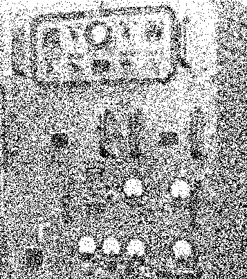
Figure 16: SG-1 main frame located in the radar equipment room. Photo: Radio magizine ca. 1945.
The main frame, containing transmitter, receiver, power supply, timer and duplexer (T-R) functions is shown in Figure 16. A very handy diagnostic oscilloscope is in the top drawer.

Figure 17: SG-1 antenna sitting on the edge of a dock. Normally this antenna is located on the mainmast of the ship. Photo: Evolution of Naval Radio-electronics, page 189.>
The antenna (Figure 17) is normally mounted high on the ship’s mainmast, about 75 feet up on a destroyer. Radio energy travels from and to the mainframe through waveguide, a rectangular hollow pipe. RF energy from the transmitter fans out from the waveguide tip and bounces off of the parabolic reflector, focusing into a narrow beam. Echo energy is focused on the waveguide end by the reflector, traveling back down to the radar mainframe. The result is a very narrow SG-1 radar antenna pattern, for good target definition, directional accuracy, and high sensitivity.
My personal impression was that our SG-1B on the U.S.S. Stephen Potter was superbly built, as are most things built to Navy specifications. In spite of its large tube complement, it was very reliable and was straight-forward for trouble shooting. As with most microwave equipment of that generation, the transmitter and receiver took some tender care and feeding. This is particularly true because a hardware failure and a tune-up goof often had the same symptoms; wrong frequency modes, low sensitivity, and frequency jumping. Antenna positioning circuits gave us quite a bit of trouble, which was something of a surprise. Depending on the problem, antenna and position indicator could disagree by 120, 180 or 240 degrees. The indicator console’s only operating inconvenience was that the PPI scope was not really positioned for long periods of close attention.
SG1-lB had a feel of true quality, and was a pleasure to operate. It was like living with a well-designed automobile.
FD (MARK-4) NAVY FIRE-CONTROL RADAR
700 MHz, 40 KW magnetrons provided the "main bang" for a generation of Navy gun-control (fire-control) radars. BTL/Western Electric not only developed and produced magnetrons; they also produced a secession of shipboard fire-control radars in close conjunction with the Naval Research Laboratory.
Exact ranging was the chief benefit originally expected. This resulted in the Model FA (Mark-1) "range-only" radar, put into operation in July, 1941. It had a conventional vacuum-tube transmitter delivering about 2 KW, which was marginal. Model FB (Mark 2) died on the drawing boards because advent of the magnetron rendered it obsolete. The next step was the FC (Mark-3), with precision azimuth control due to its horizontally lobed antenna. FC employed the new magnetron, with more-than-adequate range for surface gun control. Most technically exciting was the FD (Mark-4) radar, with the addition of precision elevation sensing by the addition of vertical antenna lobing. Here was an anti-aircraft radar accurate in range, azimuth and elevation, ideally suited to meet the growing threat of aircraft attacks.
FD was successfully tested aboard the U.S.S. Roe in September, 1941. 375 sets were built starting in 1941. They gave excellent combat performance through the end of World War II.
FD transmitter output was 40 KW at 700 MHz, with a short (2 usec) output pulse. Its total range was 100,000 yards, but gunfire did not usually start until the attacker closed to within 10,000 yards. FD automatically fed data to the below-decks gun-control computer, which in turn controlled the anti-aircraft guns. The larger AA guns, usually with 5-inch bore and 16-foot length, shot proximity shells. These shells used radio proximity fuzes that automatically exploded the shell when it was within about 100 feet of the target. FD plus proximity shells made a very effective system with a high kill rate.
FD was at its best at night or in bad weather, when optical gun control was impossible. However, FD’s range precision was far superior to that of optical ranging, and was used even in broad daylight. Range was accurate to 23 yards at 100,000 yards!
Figure 18: FD (Mark-4) antenna on Mark-37 gun director. Photo: Radar Systems and Components, page 49.
FD radar was usually operated from the Mark-37 gun director shown by Figure 18. FD did not have the luxury of a single elegant indicator console. Rather indicator elements were split up train (azimuth), point (elevation; and range operators’ positions in the crowded gun director. Figure 19 shows the range operator’s position with display unit and range unit. With this crowded arrangement the operators can shift back and forth between visual and radar tracking without missing a beat. There was also a monitor scope at the mainframe below-decks; the radar technician was an essential but unseen team member, as you’ll see later.

Figure 19: FD range operator’s position in Mark-37 gun director. Photo: Radar Systems and Components, page 29.
FD operation was straightforward. The gun director would be trained to the azimuth indicated by search radars, at an assumed elevation. The director could be slewed quite quickly until the range operator picked up the target echo. The range operator cranked the range until the target pip was in the "range notch" on his scope. These pips would then appear on the trainer’s and pointer’s scopes. The trainer saw two pips representing left and right lobe; the pointer saw two pips representing upper and lower lobe. When the left-right pips were equal, and the up-down pips were equal, the FD was right on target. As the target moved, the operators would readjust to keep on-target.

Figure 20: FD mainframe and related units. Photo:Bell System Technical Journal
FD’s mainframe (Figure 20) contained an the major functions except antenna and indicators. The key to advanced performance was the microwave system: 700 MHz magnetron, gaseous T-R switches, receiver pre-amplifiers with planar "lighthouse" tubes, and "doorknob" type mixer and local oscillator tubes. These were the super-components of that gray world between UHF and microwave frequencies. We’ve already discussed the magnetron. The gaseous T-R tube switches the receiver on within microseconds after the magnetron’s high-powered pulse, so that targets can be seen in to a range as close as several hundred yards. This is important when an attacking plane is flying right down your throat!
Personal observations: The r-f pre-amplifiers, with their GL-446A "lighthouse" tubes (so-called because of their appearance) were very sensitive and had very low noise, hence an excellent "signal to noise" ratio. That’s the good news. The bad news was that the coaxial amplifier designers had underestimated the brutal mechanical shock of destroyers firing five 5-inch guns broadside in battle. The pre-amplifiers broke into wild oscillation at the precise moment we needed the FD radar most. When enemy planes came in on us, a technician stood by the mainframe. He watched the monitor scope, and would quickly patch out the pre-amplifiers as the signal pips got strong enough. Thus we had use of the pre-amps when we needed them (tracking at longer ranges) but didn’t get into oscillation troubles at the "moment of truth".
FD had the quality you’d expect of something made for the Navy by the Bell Telephone Company; it was solid. As with other early high tech radars, the r-f system needed some tender care and feeding. The only real limitation was at low elevation, as with low-flying torpedo planes; echoes reflecting from the water tended to make the radar want to shoot into the water instead of up in the air. That’s when the gun director crew earned its pay, second-guessing the bouncing echo.
ARMY SCR-584 SEARCH AND FIRE CONTROL RADAR
Radars in the 100-200 MHz frequency range did very well as early-warning watchdogs. However, they were not accurate enough for anti-aircraft fire-control work. Advent of the magnetron as a microwave high-power oscillator produced a generation of precise fire-control radars. Though billed as a fire-control radar, SCR-584 performed both fire-control and air search roles admirably, and became the most-used air-search/fire-control radar of the war. Operating at 2,900 MHz, it had extreme accuracy combined with a range of 70,000 yards. Automatic tracking and semi-automatic range control were used.
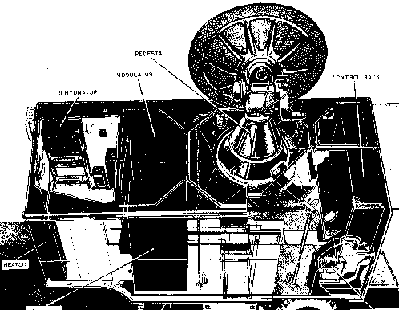
Figure 21: Usual layout of SC R-584 trailer with antenna elevated.
Figure 21 shows a large cutaway-view of the SCR-584 system. It automatically sends azimuth, elevation, range and altitude information to a gun director, which runs the firing calculations and controls the guns themselves. All that’s involved in "breaking camp" is to crank down the pop-up antenna, unhitch some wires, and stow the outriggers. This yields great mobility.
SCR-584’s magnetron transmitter provided pulses of 210 KW, 0.8 usec, with a pulse rate of 1,707 pps at 2,700 to 2,900 MHz. The parabolic dish antenna provided helical scan for air search, and conical scanning for precision tracking. This radar could detect targets up to 70,000 yards, and automatically track them as far out as 32,000 yards. Accuracy was phenomenal: +/- 25 yards in range, +/- 10 yards in altitude, and 1 mil (0.06 degrees) in azimuth and elevation.
Thousands of SCR-584’s were built. They were used in North Africa, and all the way from Anzio, Italy up through Europe. They were heavily used in the aerial Battle of Britain. Particularly, SCR-584’s were credited with knocking down a major fraction of the German buzz-bombs crossing the English Channel. This set was also a key participant in the Asiatic and American theaters of war. It is regarded as "the most widely-used and generally successful’ radar of the war by some experts.
AN/APS-3A AIRCRAFT RADAR
After completing SG shipboard search radar development, MIT Radiation Laboratories and the Naval Research Laboratory initiated development of the ASG airborne radar in the same 3,000 MHz band. This became the AN/APS-2, produced by Philco. This set was bulky, and was limited to large patrol aircraft.
Availability of 10,000 MHz magnetrons reduced antennas and magnetron hardware by a factor of three in dimensions. This meant that radar transmitter-converter-antenna assemblies could be carried in nacelles under aircraft wings. The first radar of this type, developed by the MIT Radiation Laboratories, the NRL, and Sperry, was the ASD, manufactured by Philco as the AN/APS-3 starting in 1943. The new concept was a success. Forward search azimuth was 150 degrees wide, switching to 60 degrees for homing in on targets. Ships could be detected up to 300 miles away, submarines at 15 miles, and other aircraft at 8 miles. With its type-B radarscope presentation, this many-talented set was used for search, homing, and navigation. Homing tasks included bombing, torpedo runs and aircraft interception (but not gun control). AN/APS-3 was heavily used in the weather-bound Aleutian Islands, particularly for blind bombing of Japan’s Kurile Islands.
Components of the APS-3A radar are made to be tucked variously in the airplane’s airframe (Figure 22). The usual layout was to mount the antenna and transmitter-converter unit in a nacelle or pod under the wing. Other modules were mounted in the fuselage. Figure 23 shows the control unit in detail; walking through it will help us understand the set.
From the left, TILT tips the antenna dish up or down with the angle read on the meter above the tilt switch. SCANNER controls left-right oscillation of the antenna dish at 35 cycles per minute. SEARCH-BEACON, MANUAL TUNING and GAIN are all receiver controls. RANGE switch is the distance scale selector, up to 300 miles. OPERATE-STANDBY switch permits the equipment to be immediately ready to operate, without a warm-up period. EXPAND-SEARCH permits greater accuracy when homing in on a target, and is helpful in sorting out crowded targets and ground-clutter. MASTER SWITCH turns the entire radar on or off. DEFINITION is the mystery switch; the manual just says "instructions will be issued later". However, this switch is the counterpart to anti-jam and anti-clutter switches on other radars.
This benchmark radar was used in medium-size and large Navy aircraft through the end of the war. A smaller, lighter set, the ASH, was manufactured as the AN/APS-4 by Western Electric for smaller aircraft, starting in 1944.
AN/APS-3 marked the shift to nacelle and pod-mounted aircraft radars, a long-enduring airborne radar configuration.
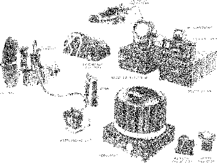
Figure 22: Components of AN/APS-3 airborne radar. APS-3A manual, page 10.
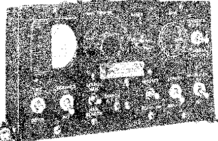
Figure 23 above: Control unit of AN/APS-3 airborne radar. APS-3 manual, page 30.

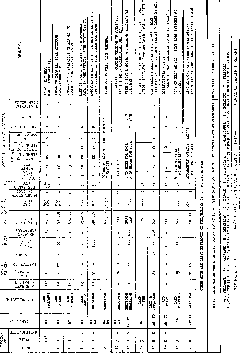
German and Japanese WWII RADAR SPECS
Click to see in large page
(The photos will be replaced when I can find the orig. these are just screen shots from dithered pagemaker file.)
FOLLOW-ON
Radar sets themselves are only a part (but a major part, of course) of the radar story. There have been many supporting, and sometimes neutralizing systems, such as beacons, IFF and radar countermeasures. Perhaps we will delve into these subjects at a later time. Also, the early history of radar is a fascinating subject. And the magnetron; perhaps the story of stories!
BTL Record (Selected radar articles), 1946-1947.
Electronic intelligence: The Interception of Radar Signals, R. G. Wiley, Artech House, 1985.
Evolution of Naval Radio-electronics, L. A. Gerard, U.S. Government Printing Office, 1979.
Five Years at the Radiation Laboratory, MIT, 1946.
A Flick of the Switch, M. E. McMahon, Vintage Radio, 1975.
Handbook of operating instructions for Model AN/APS-3 Aircraft Radar Equipment, USGPO 1945.
Handbook of operating instructions for Model AN/APX-2 Aircraft IFF Equipment, USGPO, 1944.
A History of the U.S. Signal Corps, Putnam, 1961.
M. E. McMahon (Various personal notes, correspondence and recollections; ship’s log; news clippings), Circa 1943-46.
Principles of Radar, Reintje, Coates and MIT Radar Staff, McGraw-Hill, 1952.
Radar, 0. E. Dunlap, Jr., Harper & Brothers, 1946.
Radar Days, E. G. Bowen, Adam Hilger Co., 1987.
Radar-First Fotos Released (article), Radio Magazine, v29 n8, pp 46-47, 1945.
Radar Systems and Components, BTL Staff, D. Van Nostrand, 1949.
Radar System Fundamentals, Navships 900,017 & War Dept. TM11-467, USGPO, 1944.
Radiation Laboratory Series, MIT, volumes 1-28, McGraw-Hill, 1947-48.
Radio Countermeasures, NDRC Div. 15 Summary Technical Report, vol 1, 1946 (As summarized by Electronic Warfare Magazine as "EW WW-II History").
Radio Sets SCR-584A&B Service Manual TM-11-1524, USGPO, 1946.
The Secret War, Meuthen Inc., 1978.
Swafford Papers at Southwest Museum of Electricity and Communications, Phx. AZ.
Textbook of Radar, E.G. Bowen, Cambridge Univ. Press, 1954.
We are always looking to buy books , paper, or artifacts related to RADAR and RADAR Countermeasures to add to the museum. Please contact us! Email here or 623-435-1522
