|
|
Phonics TVphone TTY
Compiled by Ed Sharpe Archivist for
SMECC
write in with more information to add
and questions to: info@smecc.org
from the patent drawing....
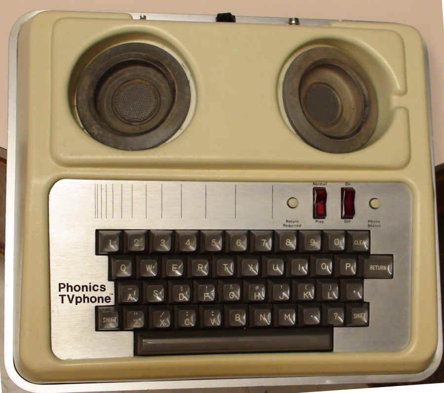
TVphone, possibly a prototype. -
RMS Industries Inc - 824 Thayer Avenue - Silver Spring Maryland -
Photo from The Harry G. Lang Collection at SMECC
|
|
From The Zimet/Black Collection at SMECC
From The Zimet/Black Collection at SMECC
|
(TVphone Ad - TDI First National Conference Program
June 13,14 & 15 1974 - From The Paul and
Sally Taylor Collection at SMECC )
TVphone™ Person
to person
Direct telephone communication is important, for feeling, meaning
and understanding. Unfortunately, the deaf and hearing impaired have
always had to communicate through someone else. There's no reason it has
to be that way anymore. Because now they can enjoy the convenience,
independence and peace of mind that comes with being able to use the
telephone themselves. With the TVphone™ connected to the antenna of any
household television, telephone communication is provided by reading the
typewritten conversation on the screen. For further information on TVphone
Service and how the deaf can make full use of the telephone at a low
monthly cost contact: Phonics Corporation, 814 Thayer Avenue, Silver
Spring, Md. 20910. Tel (301) 588-8222
 |
| |
| |
| |
|
FINAL
REPORT
NORTHEAST
REGIONAL MEDIA CENTER FOR THE DEAF (OEG-0-73-0534)
1973-1974
"A
Field Test of Electronic Telecommunication Terminals for the
Deaf"'
Raymond
Wyman, Ed.D., Director
Todd Eachus, Ed. D., Associate Director and Project
Coordinator
University of Massachusetts, Amherst, Massachusetts 01002
27 September, 1974
TABLE OF CONTENTS
I. Introduction
A. Scope
B. General Features
II. Method
A. Social Communication
1. Research Design
2. Data Collection Instruments
3. Procedure
B. Business
1. System Designs
2. Procedure
C. Educational/Systems Utilization
III. Results
A. Equipment
B. Social Communication
C. Business
D. Educational/Systems
IV. Conclusions and Recommendations
A. Equipment
B. Social Communication
C. Business
D. Educational/Systems
3
INTRODUCTION Scope
A field test of electronic telecommunication terminals for the deaf
based on the identified need for alternative communication
devices for the adult deaf population. For such a field test to
be conducted most effectively requires a large sampling base
from the population in question. The present study was
necessarily truncated due to the limited time and resources
available with which to conduct such a study. It was anticipated at
the outset of this amendment that the identification of variables likely
to be of principal concern in further evaluations of telecommunications
with the handicapped in general and the deaf in particular would
be identified. The evaluation plan which was developed for this
field test emphasized placement of telecommunication units in
the homes of deaf adults and other locations in order to
determine empirically the dimensions of telecommunications
rather than to provide a definitive analysis of the long-range
effects of such devices on the lives of handicapped persons.
The intent of this field test then is to be suggestive of the course
of future work in the area of determining the most appropriate
and effective methods and procedure for including
telecommunications for the handicapped.
3/4
General
Features
The general features of the evaluation performed under this amendment include
the utilization of a telecommunications device by the deaf in social communications,
business uses, and educational and general data systems uses. The
social communication uses of telecommunications devices received primary
emphasis in this study. The vast majority of placements of instruments
procured for this field test were made in homes of deaf adults
in the Boston and New York metropolitan areas. Each individual
who served as a participant in the field study provided data on
a periodic basis before, during, and after the utilization of
the particular equipment used in the study.
Several notions for examining the potential utilization of
telecommunications devices in business or commercial settings
were considered at the outset of this study. Ultimately,
however, it was decided on the basis of time available and
limitations of fiscal and personnel resources to concentrate on
the utilization of a telecommunication device in a retail
setting located in a region with a large number of deaf adults
already possessing telecommunications devices.
Educational and general systems applications of a telecommunications device
were examined in two ways. Units procured under this amendment were placed
in school settings at locations where the use of educational media was
relatively advanced. General systems applications were
investigated by placing units at the disposal of an institution
of higher education which provides educational services to
handicapped and other individuals through the use of a
widespread computer based instructional system.
Because of the need for expertise in survey research methods, it
was determined that the resources of the Deafness Research and Training
Center at New York University would provide most effective
expertise in determining the sampling base development of data
collection instruments, validation of instruments, and insuring that
these aspects were consistent with commonly accepted practices used in
the field.
5
II.
METHOD
Social
Communication
During August of 1973, the Project Director met with Dr.
Jerome Schein, Director of the Deafness Research and Training
Center, to, determine the extent and kind of services to be
contracted by the NRMCD. Subsequent to the initial meeting,
further meetings were held between the staffs of the two organizations to
determine the basic dimensions of the social communications
research design. Several versions of the design were completed
with a revised final version submitted to NRMCD by the Deafness
Research and Training Center on 6 December 1973.
1. Research Design
The primary goals of the project are: first, to evaluate the TV
Phone in terms of equipment utility and reliability, user
reaction, and impact and the user's self-perspective; and second,
to compare the TV Phone to presently used teletypewriters (TTY's)
on these same criteria.
The term "user" will refer to individuals only and therefore
will not include institutions. A separate research design for
institutional users and for preselected government users will be
prepared and implemented by the NRMCD.
A. Number of TV Phone Units
Approximately 95 TV Phone units will be supplied under contract by the
Phonics Corporation to the NRMCD for evaluation. However,
approximately 15 of these units will be placed with preselected
individual users (such as federal government officials, who may provide
little more than anecdotal information) or with institutional
users which will, not be included in this part of the project.
Therefore, approximately 80 TV Phone units will be available for
the thorough field testing with individual users described below.
b. Schedule
Starting November 1, 1973,approximately 8 months will remain in
the project schedule--roughly7 months for selection of the user sample,
for field placement of the units, and for data collection; and
roughly 1 month for data analysis and preparation of the final report.
We expect that the actual starting date for field placement may be
.closer to December 1or to January 1 than to the suggested
starting date of November 1, in order to properly select the
sample of users and to adequately pretest the TV Phone before placement
by members of the NRMCD staff.
c. Definition of Sample
Degree of hearing impairment is the first consideration. We
recommend that units be placed only in households in which there is
at least one deaf person. (For definition of "deaf person",
see III A, Sample Selection.) The majority of the sample will already
have TTY's in their homes; a subsample will only have the TV
Phone. We anticipate that the most significant independent
variable will be income (subgroups within the range of $4,000 to
$25,000 annual earnings.) Other important user characteristics will
be age (subgroups within the range 19-65 years), education, occupation,
and marital status
and family composition.
D. Geographic Considerations
Two potential areas for field evaluation were chosen to minimize the time
and expense of travel and communication between the NRMCD and the
actual TV Phone users. One or both areas will be chosen by NRMCD
for the actual field tests, depending upon responses from the screener
questionnaire. The areas are metropolitan Boston and metropolitan
New York City. Actual placement of the TV Phone units will be made
wholly at the discretion of the NRMCD staff.
The project will include the standard field evaluation elements:
A. Sample Selection, B. Field Placement of the Units,' C.
Collection of Data, and D. Coding and Analysis of the Data.
A.
Sample. Selection (7/8)
1. Population Base
The sample of potential users will be drawn from the lists of known deaf
persons in the three preselected geographic areas. For purposes of
this survey deaf person is one who states he cannot hear and
understand ordinary conversation through the unaided ear. The
degree of impairment will be determined by means of the Hearing
Scale used in the National Census of the Deaf Population. For a
sample of TTY users, the Directory of TTY User& will provide
the frame. All institutional entries will be eliminated. From the
remainder, successive samples will be drawn from entries in the
relevant zip code categories representing Boston and/or New York
City. The screener will be sent to each of the addresses selected,
along with a cover letter inviting participation in the field
test. Follow-up questionnaires and letters will be sent until the
quota is completed. For the non-TTY sample, the Deaf American list
will be used (excluding verified TTY users). The procedures will
be as described above.
2. Screener Questionnaire
A screener questionnaire that will be sent to all individuals identified in the
composite list described above will serve three functions :(a) When
compiled, the responses to the questionnaire will provide a
demographic profile of-the deaf populations identified in the
three preselected areas. (b) The questionnaire will "screen
out" individuals-not suitable for inclusion in the sample of
users of the evaluation, for example, because they are not deaf or
because they' have no telephone or television. These criteria will
be established by NRMCD, based upon responses to the
questionnaire. (c) The respondents to the questionnaire will form
a pool of potential users from which the project participants will
be drawn.
The usual procedure is to mail a cover letter, describing the project along
with the questionnaire; to wait approximately two weeks for responses;
and then to mail a follow-up cover letter and questionnaire. We
recommend these steps be followed in selecting the sample for this
field test.
B. Field Placement of the Units (9)
Minimally, the project staff would be thoroughly familiar with the units
to be field tested, and the units should be individually
prechecked for possible electrical or mechanical malfunction before they
are placed with the users. The users who have been selected would
be notified by mail before placing the unit. At the same time,
permission for access to the user's telephone bills (before, during and
after the field evaluation) should be requested. In addition, for
identified TTY users a short follow-up questionnaire should be administered in
person to secure preliminary data on the extent of use and typical purposes
of the participants' TTY use. The TV Phone units will be delivered
personally by NRMCD staff experienced in the use of the units. The
user will be instructed personally and in writing about the use of
the TV Phone. It is strongly suggested that several trial placements of
the units be made before the final field placements in order that
NRMCD staff learn to anticipate possible difficulties. A formal
check list should be prepared by NRMCD for these staff members.
C.. Data Collection
1. Data Collection Model
The following discussion suggests a straightforward design for apportioning and
scheduling the placement of TVPhone units in each of the three
geographic areas. Modification of the design may be necessary, of
course, depending upon information secured from the screener questionnaire. For
example, there may not be enough potential deaf users in
metropolitan Boston to fill the user quota for that area, thus necessitating
adjustment of the field test sample.
The first 20 TV Phone units will be apportioned at the discretion of NRMCD in metropolitan Boston
and/or metropolitan New York City. Each of these units will remain with
a single individual user for the duration of the evaluation period
for about 6 months. The next 60 units will remain with an
individual user for only half the evaluation period (for about
3months) before it is moved to a second user. Each unit will than
stay with the second user for the remaining 3 months of the
evaluation period. See Table 1.
Table 1
Alternative Distribution Plans Assignment of 80 TV Phone Units for
Field Test
Approximately
2/3 of the TV Phone units will be placed with people who already
have TTY's in their home. The remaining 1/3 will be placed in
homes which do not have a TTY, but which include people who' are
deaf or who have regular contact with the deaf community. see
Table 2.
|
Table 2
Field Test Sample; TTY Users Vs. Non-TTY Users
|
|
Entire
6 Months |
First
3 Months |
Second 3 Months |
Total
Tests |
| TTY Users |
13 |
40 |
40 |
93 |
| Non-TTY Users |
7 |
20 |
20 |
47 |
|
|
|
|
140 |
2.
Data Collection Instruments
(a) Screener Questionnaire
As described above, the Screener Questionnaire will be used to determine
demographic characteristics of the deaf population in each area, to
screen out potential users who cannot be included in the project,
and to forma pool of candidates from which the sample are chosen.
(b)
Leave-Behind Questionnaire
This questionnaire will have two purposes: First, it will be a
usage log for the unit, especially for the, number, duration and time
of day for local calls and whether or not the calls were user-initiated. Second,
it will include the opportunity for the user to express reactions to
the TV Phone itself and also to describe how the TV Phone is
actually used; i.e., Does it always remain in the home? Does it use
interfere with normal television viewing? Particularly important aspects are
portability, quietness, absence of hard copy, reliability and cost.
Opportunities for suggestions to improve the TVPhone will be
provided in the questionnaire, and anecdotal information about TV-Phone
use will be requested also. An essential, special supplement to the
questionnaire will be a log for recording equipment malfunction
(including the accessory television set) and repair of the unit. A
second version of the Leave-Behind Questionnaire will be designed especially
for TTY users and will be used in parallel with the version supplied
to TV Phone users.
(c)
Electronic Recording Services
Measuring devices built into the individual TV Phone units will record
the cumulative time for all calls and can be monitored remotely by a
master console located at NRMCD. Monitoring will proceed according
to a predetermined schedule.
(d)
Telephone Bills
Telephone bills will provide information about certain long distance calls
(duration and time of day of user-initiated calls and of collect
calls) and in some cities will provide the total "message units"
of local calls. Comparison of telephone bills before, during and
after the evaluation will indicate changes in telephone use during
the evaluation period.
(e)
Final Questionnaire
This questionnaire will repeat several key questions regarding user reaction to
the TV Phone which were included in the earlier screener questionnaire. This
questionnaire will also attempt to determine in a preliminary way
the impact of the TV Phone ln the self-perspective of the user. As
suggested by NRMCD staff, the measures of this self-perspective will include
real and perceived social and economic independence, feelings of
security, self-satisfaction, etc. Ample opportunity will be provided for
suggestions for equipment modification.
D. Analysis of Data
Broadly stated, the major dependent variable of the study is user reaction to
the TV Phone. It can be defined according to three distinct
measures, each of which should be included in the evaluation:
To
what extent does he use it?
How much does he like it?
What will he pay to purchase or lease it'?
Refinements of these three measures will be accomplished through the
use of the several survey instruments already described above: the
Leave-Behind Questionnaire, the electronic recording device, the
telephone bills, the final questionnaire, and the repair records. We
anticipate that the most important independent variable will be income,
but that age, education, sex, and marital status may also provide
useful correlations. The preliminary sample will consist of current
TTY users and non-TTY users. The TTY users will be further divided
into Group A, which will receive TV Phones and Group R, which will
become the control group and therefore will receive none.
Similarly, the non-TTY users will be divided into Group C, which
will receive TVPhones and Group D, which will not, ( Group D will
be omitted from the final data sample.)
Similar analyses of data will be performed for each of the sample groups,
A, B, and C, and then the results will be compared by means of
multivariate analysis, Further analysis, such as the' change in
user reaction over time, will be dependent upon the nature of the
collected data.
**********
We recommend four general approaches to the study of the TV Phone:
1. Questionnaire Items
These items must be designed to elicit basic demographic
information, including income, age, education, sex, and so forth. In
addition, user evaluations and attitudes should be solicited. Several
dependent measures should be gathered at fixed intervals, minimally
at the beginning and the end of the evaluation period. The purpose
is to determine user reaction to the TV Phone both at the
initialcontact and after extensive use. In this way both consumer
resistance and consumer acceptance can be evaluated.
:additional measures before initial contact, during the evaluation period, and
after the instrument has been removed could provide further measures
of these user reactions.
2.
Objective Measures
Through the use of questionnaires and telephone bills a determination can
be made of telephone use before, during, and after the evaluation period.
A t test for correlated means will be used here.
Electronic recording devices on the TV Phone will be used in conjunction with
telephone bills and the Leave Behind questionnaire to compare the use of
the TV to the use of the TV Phone for selected users who have access
to either or both during the evaluation period.
3. additional Evaluation Items (15)
These items may be solicited from the user by a combination of written questionnaires
and by personal interview, probably at the very end of the evaluation
period to coincide with the administration of the Final Questionnaire.
Items might include: Do members of your household object to your
using the television for your telephone conversations 'Do you deliberately schedule
your telephone calls to avoid competition with the family for the television? Do
you mind that others can follow your private conversations when it
is displayed on the television "Now reliable do you believe the
TVPhone is (as compared to the actual repair records)'- How can the
TV Phone he improved for your use. Technical Evaluation Staff
members should make extended use of the instrument. It should be
tested with a full variety of commonly available television receivers
and with all possible. accessories, such as audio-cassette recorders
which permit permanent recordings of TV Phone conversations.
Complete records of the duration and cause of instrument malfunctions are
essential as are records of repair. We strongly suggest, therefore, that
all requests for repair or technical assistance come directly to the
NRMCD and not to the manufacturer of the instrument. It would then
be the responsibility of NRMCD to determine the nature of the
malfunction and to repair the instrument or to engage the assistance
of a third party to
determine the malfunction and/or "to repair the instrument.
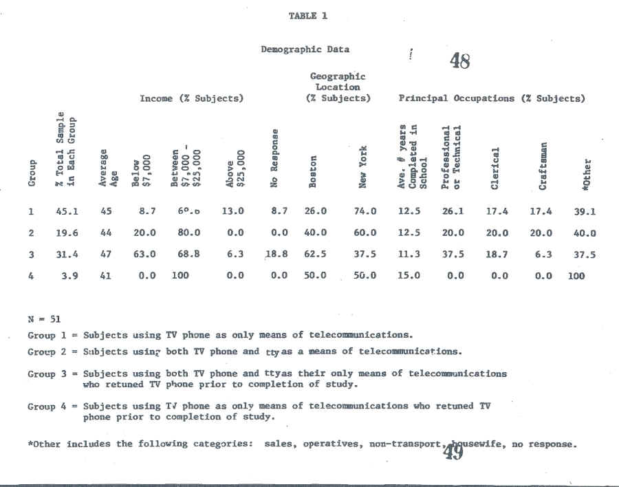
2.Data Collection Instruments
Throughout the random sample field test of social communications,
several instruments were utilized for the collection of data in each phase
of the study. As described in the design section, the initial data collection
instrument which was a screener, was used to obtain basic
demographic data on individuals identified as deaf through the TTY directory
and the national census of the deaf data housed at Deafness, Research and
Training Center. The second data collection instrument provide data
on users selected to participate and who elected to participate as
subjects in the final sample of the study as a whole. Items on this
questionnaire were concerned with subjective estimates of the worth
of the instrument; items concerned with various uses of the
instrument, and items concerned with self-perceptions of independence
of users. This questionnaire was repeated in a changed form for each
of the sample participants at the end of the usage period for each component
of the sample. Because certain individuals who were initially elected
to participate in the sample subsequently returned their instrument prior
to the planned completion of a usage period, separate data
collection instruments for early returns were prepared. In addition,
a repeated measures on-line interview schedule was utilized
periodically to determine changes in certain aspects of utilization of
the instrument with actual use.
In addition to these basic data collection instruments utilized with
the participants in the sample, there were other sources of date. Each user
was polled periodically to get an electronic count of the amount of time
the instrument was actually in use during the study period. Also, records
were kept on the electronic and mechanical failures.
3.Procedure
In establishing the sequence of events to complete the field test evaluation.,
several related steps were followed. Beginning on the date of the
initial request for amendment 25May 1973, an initial conceptual design
for tilt-field test was developed. This conceptual design was later
refined into the actual operational steps which were followed in the
evaluation project. Precise definition of independent and b dependent variables
and their measures was completed in September of 1973.Becauseof tilt
4.gportance of insuring that good random population sampling
procedures were followed, where possible, a consulting relationship was established
on 21 September 1973 with the Deafness Research and Training Center
in order to draw upon the cumulative expertise of the staff of the Center
in sampling procedures among the hearing impaired. Earlier meetings with
the staff of that Center had led to the development of data collection instruments
and subsequent revision by 30 September 1973.As part of the consultant
services provided by Deafness Research and Training Center, these
instruments were then field evaluated with a control population by 5
December1973.On 6 December a revised field test design was completed
and forwarded to the project officer.
The initial identification of the population sample for the study was completed
on 20 September 1973.On 30 November 1973, mailing lists of the sources
for the population sample were derived from subscriber lists of the publication,
Deaf American, and from Teletypewriters for the Deaf, Inc.,
inclusive of the Boston and New York metropolitan statistical units.
From the lists of individuals Identified in the sources of information for
population sampling, au initial mailing of an introductory letter, a
screener questionnaire, and return envelopes was sent to all households on
the mailing lists by December 14, 1973.Responses were received from this
initial mailing from 15 December to 28December 1973.
On 21 December 1973 usage logs and equipment malfunction logs to bemused
by all subjects of all three tests groups were developed. These logs were
duplicated on January 2, 1974.
Responses from the initial screener questionnaires were tabulated and
keypunched and sorted for frequency by design cells by 15 January
1974.When the sort had been completed, a set of key questions to be
used during an on-line data collection process were completed and a
schedule for administering these questions was made. Each household
selected to serve in the final sample for the study was located geographically
by the end of January. A design was completed for the placement of instruments
with each household serving in the final sample.
By 4 February 1974, a written list of instructions concerning the
installation and use of the equipment in the study to accompany the distribution of
each piece of equipment was developed. These steps were completed by
4 February 1974.Between the Fifth of February and the Thirteenth of
February, locations for meetings of study participants were identified so
that initial training for installation and use of the equipment
could be conducted and that questionnaire administration could be completed. By
13 February1974, letters announcing to the individuals, their selection in
the sample, and the time and location for distribution meetings was
completed.
(pp19) Prior to conducting the initial placement and data collection meeting son
March 16th in the Boston area, and March 23rd and 24th in the New York metropolitan
area, project staff had been trained to administer the initial data
collection instruments and to demonstrate equipment operation and
hook-up. On 16 March and 23 and 24 March, initial placement meetings were
con-ducted in which each individual user completed the initial data collection process
and received hands-on instruction in installing and operating the equipment
to be used in the study. In addition, the calling times for electronic
duration polling and on-line data collection were scheduled with each individual
user. Following these meetings, those individuals who were selected
for the final sample but were unable to attend the initial placement meetings
were mailed the initial questionnaires and their equipment for
participating in the study. This was completed by March 29, 1974.
From April 8 to July 14, electronic frequency polling and on-line questionnaire
data were collected from users in all of the groups in the study. From
25 March to July 14,usage logs were collected by mail from all participants. From
the time of initial placement to July 14,parti-cipants in the study
were called and did call project staff concerning problems of
equipment malfunction, misunderstanding, confusion, etc.
In the early phases of placement, several people selected for the final
sample who did receive instruments returned them for a variety of reasons
and replacement households were identified to participate in the study. On
July 6 and on July 13 and 14, 1974,regional meetings were conducted
in the Boston and New York metropolitan areas to collect all
TVPhones and for the administration of final data collection
instruments at the end of the study. By August 14 those individuals participating in
the study who were unable to attend the regional meetings were individually contacted
and their equipment was collected and final questionnaires were
distributed. All equipment was collected from users by 19 August. Key-punching
and coding of all data from questionnaires, logs, and periodic
on-line questionnaires was conducted from 21 to 22 August.
Business
(pp21)
Several alternatives were explored for examining the potential use of
electronic telecommunications devices for the deaf in a variety of
business organizations. Among the alternatives given consideration were
the placement of equipment in personnel departments of organizations
employing large numbers of deaf individuals in certain metropolitan
areas. In addition, consideration was given to providing equipment
to state departments of police and medical service agencies. Because
of the short amount of time available for conducting this project,
many of the possible alternatives for examining utilization of electronic telecommunications
devices and business settings had to be forgotten.
1. Systems Design
One member of the National Advisory Committee on the Handicapped is representative
of the business community. This individual is Ms. Katherine Breen,
who is director of training for Montgomery Ward, Incorporated. After having
received the description of the basic nature of the evaluation
project from BEH personnel, Ms. Breen communicated with me her
interest in exploring possible utilization of telecommunications equipment
for the deaf by Montgomery Ward. Between 5 and 8 March an initial meeting was
held between the evaluation project director and personnel in
Montgomery Ward' corporate headquarters in Chicago. It was
determined that an area of exploration for which a usage system was
to be developed was that of retail catalogue sales within the
Chicago metropolitan area. As true of all large catalogue sales
organizations, Wards provides telephone ordering services to its customers. In
this case Montgomery Ward's operations are regionalized with one
region serving the Chicago metropolitan area. .Catalogue sales orders
are received by telephone at a central location adjacent to corporate. headquarters
in Chicago proper. A staff of approximately 30 individuals receives
orders on individual telephone extensions from a central system and
these are processed through CRT display to a computer control
ordering unit. It was determined that through the simple expedient
of installing one of the electronic telecommunication devices being evaluated by
this project and training Ward staff to operate it, that hearing impaired
individuals could, by dialing a dedicated line, conduct their retail
purchasing business through normal catalogue sales operations.
The complex issue which was involved in obtaining Ward's participation
in this aspect of the evaluation study, was to insure the willingness to
cooperate at the corporate vice-presidential level. The decision to participate
in this evaluation was based largely on the feasibility and lack of
potential disruption of ongoing operations at the regional catalogue
sales office. Approval was granted by the vice president for catalogue
sales of Montgomery Ward's corporate headquarters.
Proceeding from that point, a system was designed which involved the
placement of electronic communication devices in the catalogue sales office
to receive calls on a dedicated line from hearing impaired individuals utilizing
TTY communications. Staff from Montgomery Ward's catalogue sales telephone
office were trained in the installation and utilization of the communications
device and a unit was placed in the catalogue sales store in
downtown Chicago to provide for those hearing impaired individuals
on a walk-in basis.
2. Procedures (pp23)
One major concern in completing this installation was in devising means
to inform hearing impaired individuals, with access to a TTY,
avail-ability of this service. On the basis of zip code numbers, TTY
users were listed from the TDI directory and provided to Montgomery
Ward catalogue sales personnel. Each individual on the list
(approximately 412 in the expanded Chicago metropolitan area) received
from Montgomery Ward a letter introducing the telecommunications service
and a copy of the current Montgomery Ward catalogue. In addition,
the National Fraternal Organization of the Deaf was notified as were
the individuals concerned with a coincidentally scheduled meeting of
all TTY-users in the Chicago area.
On May 7 Montgomery Ward Public Relations Division conducted a press conference
which resulted in distribution of the information about the service
through newspapers, magazines and television news services (including
captioned news for the deaf) in the Chicago metropolitan area.
Data on the feasibility of this type of business service to the deaf community
were obtained by recording the number of calls received and orders
processed through this service.
Educational/Systems
Utilization (pp24)
At the outset of this evaluation study, it was determined that effective
evaluation of electronic telecommunication in educational settings could
not be thoroughly evaluated in the time available for this project. Exploratory
applications of the communications equipment were provided by the
Media Departments at the Clarke School for the Deaf and the American School
for the Deaf. Communications equipment, were placed at the disposal of
these schools for study as possible educational tools in dormitories, infirmaries,
study halls, tutoring in homes of students too ill to attend classes
and for two-way programming over existing close circuit operations.
In addition, the State University of' New York's Instructional
Technology Department agreed to examine the utilization of the
equipment for possible use as an on-line computer terminal for
handicapped individuals confined to home and in other applications. The
technical modifications necessary to make the equipment evaluated compatible with
time sharing computer systems was explored. This aspect of the evaluation study
was a collaborative effort between this Center and Dr. Norbert
Nathenson, and various agencies of the State University of New York system. It
was felt that this application would provide implications for the general systems
use of an educational nature. In addition, implications for possible applications
of electronic telecommunications devices in management information
systems and elsewhere would be determined.
III.
RESULTS
The results of the evaluation study will be presented in several parts. The
first part will be concerned with the procurement and functioning of
the equipment used in the evaluation study. The second part will present the
findings from the data on social communication. The third part will present
information on business applications, and the fourth part will
pre-sent information on educational systems applications.
Equipment
Upon receipt of apps,a1 for this amendment request and the specified funds
on 21 June 1973,a set of functional specifications for equipment to
be field tested were developed. These specifications were completed
on27 June 1973.The University initiated the competitive bid procurement process
for the telecommunication equipment on 5 July 1973.Through this process,
the functional specifications were distributed to prospective bidders
either identified by BEH or through normal procurement channels of
the University of Massachusetts. Bids were received on 9 August
1973, and the contract was awarded. to Phonics Corporation of Silver
Spring, Maryland on 15 August 1973.
Following award of this contract for the purchase of 95 "TV Phones," other
steps had to be followed prior to receipt of the equipment. The
con-tract was awarded to purchase 95units at a price of $915 each with normal
warranty. One of the units which was to serve as a master control
unit included additional electronic circuitry to enable polling of
the units to be placed in the field. Polling would activate on the
raster a set of binary digits which would translate into cumulative running
time of each unit. The electronic counter unit cost $72for each instrument. The
University of Massachusetts required a performance bond by November
1973.
Of those units received, 25 of the 95were defective for one reason or
another and returned to Phonics Corporation for repair. This delayed
the initial placement of units due to the time required to teat
fully the performance of each of the instruments prior to placement
in the field. These performance tests were completed for all 95
units before 1 February1974.
One of the inherent assumptions basic to exploring the utilization of electronic
rather than electro-mechanical communication devices for use by the
deaf and other handicapped persons is that the reliability of electronic equipment
is expected to be higher than that of electro-mechanical equipment.
While no direct comparison was made of relative frequencies of repair and
maintenance between the two types of equipment, the fact that 26.3
percent of the units procured with which to conduct this field evaluation arrived
defective in one way or another indicates the need for further
developmental work in a manufacturing processes for such equipment.
One 28 January 1974, NRMCD received a letter from Mr. Ronald G. Moyer, president
of Digilog Systems, Incorporated. The letter stated that on 15
March, 1974 Digilog Systems, Incorporated entered into formal contract with
Phonics Corporation whereby Digilog granted to Phonics certain
licensing rights for the use of engineering plans, drawings and specifications developed
by Digilog on certain telecommunications equipment. Mr. Moyers
stated that:
"We hereby regret to inform you that due to certain contract
violations Digilog has withdrawn the licensing privileges previously
held by Phonics and until or unless these violations are corrected,
Phonics (or its predecessor OS Industries) no longer has the right
to sell, lease, or rent "TV Phones" equipment or any
similar equipment based on Digilogs designs or subsequent
improvements thereon."
The receipt of this notification caused considerable concern over the possibility
of continued availability of the particular instrument with which we
were concerned. In addition, questions regarding the availability of
parts, maintenance and repair services for the TV Phones required
resolution. In consultation with the attorney for the University of Massachusetts,
inquiries were sent to the project officer, the president of Digilog
Systems, Incorporated and the president of Phonics Corporation requesting
clarification of the issues raised by the action of Digilog Systems,
Incorporated against Phonics Corporation. The only response received
to our inquiries concerning continued availability and service for
TV Phones was from the president of Phonics Corporation. No response
was-received concerning future proprietary interests from Digilog
Systems, Incorporated nor was a response received from Bureau of
Education for the Handicapped legal staff concerning contractual
obligations of the University and by the University. It must be
concluded that this issue remains unresolved.
Several times throughout the course of this study, instruments placed with
individual users failed to function for a variety of reasons. Many times
equipment did not operate effectively because of a user not
following carefully the instructions provided in a printed form with
their unit or at the initial distribution meetings. However, there
were other problems which arose following the equipment performance
checks performed by our staff. Among the component failures which occurred were
the following: individual letters would not generate characters on a
TV screen. In many cases this failure could not be detected in the
test laboratory for equipment operated by Phonics Corporation. The
switch on the TV Phones which serves to clear the screen of letters
failed and had to be replaced. Diodes failed in certain units and transistors failed
in pick-up microphones. In one case the circuit fuse in the TV Phone
unit required rewiring.
Upon inquiry we determined that the normal service policy of Phonics Corporation
is to ship a new unit to a customer upon receipt of a defective instrument. In
the case of the units utilized in this study, each of which was
specially modified to include an electronic polling counter, same day
repair service could not be provided. Those cases where a unit had to
be returned to the equipment supplier for repair or maintenance, the average
turn around time for repair of the unit was approximately, two weeks.
Generally, relationships with the equipment supplier, Phonics
Corporation, have required for the purposes of this study an
inordinate number of telephone calls between Silver Spring and the University. Phonics
Corporation licenses for assembling and repair of units, a division
of the American Machine Foundry Corporation in Alexandria, Virginia. And
apparently, as noted above, they have received manufacturing rights
from Digilog Systems, Incorporated. In a normal course of business,
Phonics Corporation can be considered a relatively small equipment supplier
when compared to suppliers of more generally available electronic equipment. It
is assumed that due to the size of the organization supplying the TV
Phones to this study, certain disadvantages and advantages accrued
to the project. Among the advantages was that direct contact could
be maintained with the president of Phonics Corporation as
difficulties arose in dealing with malfunctions or failures of equipment. Among
the disadvantages was the fact that there is only one location in the country
from which and at which the equipment can be received and repaired.
Social
Communication (pp30)
Items were included on questionnaires given to users concerning mechanical
functioning of the TV Phone instruments. on the mechanical
functioning of these instruments were obtained primarily from two sources: the
individuals initially chosen as members of the study sample who
returned the instruments prior to completion of the designated
period of use, and those individuals who utilized the instrument
throughout the designated period.
Of those individuals who returned their instruments early,
11categories were utilized for identifying reasons for the early return. A
total of eighteen individuals did not complete the stated period of
use of the TV Phone. Of those eighteen, sixteen were at the time
also TTY users. By far the greatest frequency of reasons given by
these individuals for returning the TV Phone appears as Item 11 in
Questionnaire #5.This Item is a simple statement that they would rather use
the TTY, followed by an open-ended explanation. Prior to discussing those
reasons, the less frequently used categories will be described.
Item 1 on Questionnaire #5 indicated a lack of understanding of the
installation of the TV Phone. Two TTY users and 1 non-TTY user indicated
that this was the reason for their return of the instrument. Item 4
on the questionnaire was a statement that the TV Phone did not work properly. Three
TTY users indicated that this was the reason and two non-TTY users
indicated improper operation as a reason for return. Item 5, a
statement of dislike for a lack of permanent record of the the
conversations, was indicated by six of the TTY users and none of the
non-TTY users as a reason for return. Items 6 and 7 indicating
respectively, a concern over an undue increase in phone bills and a lack of
individuals to call were indicated first by one non-TTY user, and secondly,
by two non -TTY users. No TTY users indicated that these categories
were reasons for returning the TV Phone. Item 8 was indicated by two
TTY users. Item 8 expressed a concern with individuals in the family
or others directly observing the conversations being held by the individual.
Item 9 was .indicated by four TTY users which expressed that the
family members of the user objected to having TV program interrupted
while telephone conversations were taking place. Obviously, multiple
responses were given for reasons for returning the TV Phone instruments.
A summary of responses to the open-ended item for early return of a
TV Phone indicated some repetition of other items on the questionnaire. The
major reason for preferring the TTY to the TV Phone was that the TTY
supplied subjects with paper copy and the TV Phone did not supply a
paper copy or a permanent record without the attachment of a dedicated cassette
recorder. One subject felt the message on the TV Phone was often
confusing and the inability to look back at the beginning of the
conversation to reduce the confusion was seen as a disadvantage by the
subject. Other subjects wanted paper copy so that they would have a
permanent record of conversations to refer to in the future, to save for
friends, for relatives, or to read at their leisure. Another subject
noted that with paper copy, one had a record of addresses and phone
numbers. Subjects also indicated that it is difficult for a deaf individual
to copy this information from a TV screen because the movement of
the message cannot be stopped easily. Another subject preferred the
TTY because she used the punch tape attachment to record the
"Deaf Messenger" and reproduce it for friends who called
her.
A number of the subjects had difficulty adjusting their TV sets so
that they could read easily the print produced by the TV Phone. People
who did not use a separate TV for their TV Phones, found the
interruption of TV programs to be a major point of complaint. Subjects
complained because the unit is not self contained and therefore
there are three parts to the system liable to failure; 1) the
telephone, 2) the TV phone, and 3) the television set. Subjects not
using a separate TV set for their TV Phones, found that they could
not answer calls quickly enough because of fine tuning adjustments to
the set itself that had to be made. Statements were also included in response
to this item that unless solid state television sets with instant
"on" capability were used, the warm up period for tube-type television sets
delayed answering telephone calls. One interesting response to this
item concerned the typing skills of users. Some people were
concerned about the expense of utilizing the TV Phone that might be incurred due
to very slow rates of typing. However, this objection would apply to any
instrument requiring use of a typewriter keyboard by those
individuals.
Of those individuals who completed the full period of use scheduled in
the design for the TV Phone, it can safely be assumed that there was a
basic satisfaction among these users with the instrument. However, certain
general summary statements can be made which were drawn from the
open-ended items included in the final user questionnaires.
Only one subject reported having problems installing and
with operational condition of the TV Phone. This was due to this individual's difficulty
in locating a television set that would function properly with the
TVPhone. This is most likely due to initial attempts to utilize an older tube-type
black and white set that most likely had not had its VHF tuner cleaned
for a long period of time.
A number of problems in using the TV Phone were described. One subject
complained that the warm up time required by his television set
pre-vented him from answering telephone calls immediately. Several subjects mentioned
that the phone signal light did not work. The phone signal light is
a white indicator light for status of dial tone, busy signal or
phone ring. The chief complaint mentioned by most all subjects was that
numbers were often received instead of or mixed with letters.
In response to the item asking users to state the thing disliked most about
the TV Phones, the most common complaints centered on utilizing the television
set commonly used for family entertainment. Subjects did nutlike
interruptions of television programs or delay in answering calls caused by
hooking up the TV Phone connector to the television set and also the warm-up
period commonly experienced by users who had tube-type television
sets was disliked. Many subjects had older, poorly maintained television
sets which made it difficult to read the TV Phone message. Some subjects found
reading a message from a TV Phone to be a subjective strain on the
eyes. Almost all subjects complained about the absence of paper copy
or another form of permanent record for telephone conversations.
Subjects also complained about using the return key when communicating
with a TTY unit in a telephone conversation, and about the lack of
reliability of the instrument with respect to random generation of
numeric characters intermixed with letters.
The features that users indicated which they most liked about the TV
Phone centered on the compactness, portability, quietness, and ease of operation.
All *subjects mentioned (whether they were current TTY users or not)
that the principal advantage of the instrument was due to its basic
purpose--that is, to communicate directly with deaf friends, and relatives.
The major reason given by subjects for preferring the TTY to the TV
Phone was the presence of hard paper copy of telephone conversations with
the TTY and that the TTY is a self-contained unit.
Several suggestions for improvement of the TV Phone were given by subjects.
Among the suggestions were some changes to reduce the random
generation of characters which is most likely due to phone line noise
in the hertz range which activates the TV Phone. One subject
suggested that the TV Phone have an 80 character keyboard instead of
a60 character one, so it would be more compatible with a TTY. Some
subjects thought that a clearer instruction bookie-, would bean improvement. Other
subjects indicated that they would like to see some kind of paper copy
produced by the TV Phone which could not be accomplished without a
basic design reconceptualization of the instrument. One subject
indicated a desire for some kind of answering service to be provided
with telecommunications devices. Questionnaire #4 was an on-line
interview which was conducted using the TV Phone during a time instruments were
placed with users. A total number of 36 subjects were interviewed
during the study and some of these interviews were repeated during the course
of the study. A total of 84 telephone interviews were conducted. The
first item in the interview concerned the repetition of the subjective
estimate of the worth of the TV Phone by users. In the initial
questionnaire and in the final questionnaire, as well as during the
on-line interviews, subjects were asked to place a dollar value that
they would be willing to spend to obtain a TV Phone had it not been
loaned to them for the purpose of this study.
Thirteen point eight percent (13.8%) of the subjects responding
placed a value from $0 - $100 on the TV Phone. Sixty-three point
nine percent (63.9%) of the subjects placed the value between $101-
$300.Twenty-twopoint two percent (22.2%) placed the value of the TV
Phone in the category ranging from $301- $700.
The second item in the interview asked for a subjective estimate of
the importance to the individual that a copy be available to store conversations
conducted on the TV Phone. No mention was made in this item
regarding the format of the copy. Nineteen point four percent
(19.4%)of the subjects responding indicated that it was slightly
important to have a copy of conversation. Twenty-five percent (25%)
indicated that it was important, and sixteen point seven percent
(16.7%) indicated that it was very important to have a copy of
telephone conversations.
In order to tap subjects' perceptions of increased self-reliance and
independence, two items were included as probes Item 3 asked if
subjects felt that if they owned a TV Phone would they be able to
earn more money. Fifty-two point eight percent (52.8%) of the
subjects responding indicated that they did not feel that they would
be able to earn more money. Eight point three percent (8.3%)
indicated that they would be able to earn more money and
thirty-eight point nine (38.9%) of the subjects were uncertain. This
large percentage in an uncertain category indicates a likelihood of
change toward a "yes" category if the duration of the study had
been longer.
The fourth item concerned perceptions of safety with respect to the
subject providing assistance to family or friends in times of emergency. Of
the subjects responding, eight point three percent (8.3%) indicated
that they never felt safe. Thirty point six (30.6%) indicated that
they sometimes felt safe, twenty-two point two (22.2%) felt safe, and
thirty-eight point nine (38.9%) of the subjects indicated that they felt
very safe in times of emergency with the availability of the TV Phone.
Two open-ended items were included in the on-line interview which were
replications of prior items concerning liked most and liked least features
of the TV Phone. Responses were identical with those given to
questionnaire items concerning mechanical functioning of the instrument
discussed above.
In the area of exploratory utilization in educational and systems settings,
a total of 19 instruments were placed in settings alternative to the
basic research design for evaluation of social communication among
deaf adults. Before describing specific applications identified, information
similar to that derived from users in the field test concerning
problems, likes, and dislikes will be described for the alternative users.
The instruments were utilized in several broad categories: used by the
chairman of the Connecticut State Committee on the Deaf to provide direct
communication with individuals and agencies within the state of
Connecticut; used as an information resource index tool for deaf
professionals; used by student sat a residential school for the deaf
for communication between facilities at the school and with parents;
used to provide
an evening news summary on a local basis; used by a PBS affiliate
for a fund-raising auction; used by a field agent for the New York State
Bureau for Physically Handicapped Children to provide statewide
communication with various agencies and individuals concerned with
the deaf and in certain other settings for area wide utilization of information systems
notably at the Southern Regional Media Center for the Deaf.
In general, all alternative users complained that the performance of
the TV. Phone was erratic. Many felt that all of the
"bugs" had not been sufficiently resolved. A chief complaint was
that, as was true with individual users, numbers were often mixed
with letters. Reception was sometimes a mixture of characters that
was cleared if the message sender repeated the previously typed statements.
Users
found it inconvenient to have to use the return key on a TV Phone
when communicating with a TTY. Only one user complained that the
equipment was not compatible with other than standard model telephones and
could not be used with
trimline
and princess phones. Another user found that he could not get reliable recording
and playback with the hardwire coupling provided with the instrument. One
user complained that the keyboard stuck, particularly in humid weather.
The characteristics most liked by the alternative users were principally
the ability for special information agencies and individuals to
maintain direct communication with their institutions and other agencies involved
in professional work. Many alternative users liked the fact that the
TV Phone is smaller and quieter than the TTY. Most felt it was easier to
type on a TV Phone than a TTY, possibly due to the obvious difference between
a mechanical and an electronic keyboard. Some users indicated that
the automatic carriage return feature on the TV Phone was a positive convenience
relative to TTY. The fact that the TV Phone does not intrude on
surrounding activities in business and educational settings and that
a larger screen display is possible with a TV Phone than on a TTY were described
as positive attributes of the instrument. Users also pointed out
that the keyboard configuration on the TV Phone does not require a
shift key depression to generate characters such as question marks, the number
one, etc.
Among these alternative users the disadvantage of interrupting
on-going use of the television set when telephone calls are received
was indicated. It was suggested that in all cases the TV Phone be
used with a solid state television receiver dedicated for use with
the TV Phone alone. Some users disliked the lack of a permanent
record of the conversation without ancillary equipment.
Several suggestions were made for other uses of the TV Phone. The
major alternative use which was suggested was to provide emergency
services for the deaf. It must be presumed that the availability of
an
emergency
notification service by the manufacturer of the TV Phone was not
known to these users, or they felt that a service should be provided on
a local basis. Some individuals suggested that the TV Phone be
installed in public booths at transportation terminals. Other alternative uses
suggested were that the TV Phone be used to provide information about news,
area activity, social etiquette, health problems, and as a means to
provide continuing education for deaf adults, or as
a language teaching tool in Schools for the deaf.
Business
As described in the procedure section, the primary business installation
of the TV Phone was done at Montgomery Ward's Catalog Sales Regional
Sales Office in the Chicago metropolitan office. The results of this application
are different in kind from those obtained through the utilization of
questionnaires and other data collection instruments. The
involvement of a large corporate entity in a
service to the handicapped normally consists in a job placement
program rather than in providing a direct service to customers.
Of principle concern to the corporate decision making process throughout
the course of this application was to minimize the disruption of
ongoing activities directly attributable to the extension of retail sales
services to a small component of the total possible retail market. The
various decision makers involved in Montgomery Ward's operation found that
the company required no inordinate expenditure of capital or staff time
to engage in this broadened service to the handicapped. That is, functionally
the only requirement placed on the operation was the addition of two
pieces of equipment. Staff functions normally delegated in catalog
sales remained identical to those provided for a non-handicapped market. The
operation and reporting requirements for processing the catalog
sales made by deaf individuals did not deviate at all from normal
processing procedures.
The utilization of the service by the deaf community in the Chicago metropolitan
area, as might be expected, began slowly. However, after the service
was available for two weeks the impact of the efforts to communicate
the availability of the service resulted in an increasing
number of catalog sales orders being placed by telephone.
Beginning with approximately three orders per week being placed, the
rate in-creased over the study period to a point at which eight to
twelve sales orders
were received each week.
An interesting sidelight from this particular operation was telephone
calls received by the sales personnel at Montgomery Ward which were
not directly concerned with the ordering procedure. Rather, deaf
individuals occasionally would call the Montgomery Ward sales office
to simply chat with the individual manning the TV Phone. The positive
affective results generated by social communication occurring enhanced
measurably the understanding and appreciation of handicapped people
in general and deaf individuals in particular by the staff at
Montgomery
Ward.
Educational
Systems (pp42)
Several
exploratory applications of the TV Phone in general educational
utilization were made. These applications were made in the sense of
exploratory work only. Of importance from these applications were
several functions which the TV Phone could be used to provide extended
educational opportunities within a deaf community.
The need for opportunities for continuing educational programming
for deaf adults was clearly identified. It was determined that within two
metropolitan areas, hearing impaired adults could profit from
courses in further language development, reading, consumer
education, social studies (with emphasis on current events), and
various job-related skill areas. It was suggested that schools for
the deaf could be the focus for a system of continuing education and
provide educational programming through the use of telecommunication
instruments.
Another function that was identified as appropriate to be met by the
utilization of TV. Phones in schools was to provide communication
between dormitories and a teacher on duty during the evening study hours. This
type of application would provide direct contact between a teacher and
students to clarify, reinforce and assist students in completing
their academic assignments.
Another need identified which could be met through the utilization of
the TV Phone or similar telecommunication devices was to provide supplementary
instructional assistance in day programs for deaf children.
A day program could, for selected students, provide an instrument such as
a
TV Phone to be transported home in the afternoon and utilized for direct
communication with an assigned teacher during the afternoon and
evening hours.
The last need identified as appropriate for further development of
telecommunications with the deaf is for providing educational activities
to students confined to an infirmary or to their home during periods
of illness. Ordinarily, assignments of materials and information
must be transmitted by mail or through an itinerant teacher. It was
anticipated that a system could be developed for utilizing telecommunication devices
which would minimize the degree of staff time involved in ensuring an
absence of disruption in the educational progress of deaf children due to
illness.
One major area of exploration for the utilization of portable
telecommunication devices in an instructional setting was to
determine the possible use of such devices in conjunction with a
computer assisted instructional system. In this study TV Phones were
placed with the University of New York system for examination as a
possible inexpensive computer terminal for use in conjunction with a
time-sharing computer system. It was initially planned that this section of
the report would be composed by the staff of the Center for
Instructional. Resources, the State University College, New Paltz,
New York. Due to unforeseen circum-stances, the Director of that
Center couldn't complete in detail the evaluation of the TV Phone as a
remote computer terminal. However, certain general findings were
determined by his staff.
Generally, the TV Phone in its present form could, with an ancillary
device,
be utilized as a computer terminal in limited applications. There
are three areas of concern in order for a commercially available telecommunications
unit to be utilized in this way with respect to a
large scale computer system. These areas of concern center on
hard-ware computer language and available computer assisted instructional
programs.
Technically the TV Phone is limited in its operational capacity relative
to more expensive and elaborate computer terminals. The number and
type of characters generated by the existing unit
are not in all cases directly
compatible with many computer operations. Also, the hertz range for
the modem presently employed in the TV Phone is different from that used
by time-shared computer systems. The ancillary hardware necessary to
change the hertz range of the TV Phone modem to that used by most computer
systems would require an individually designed "black box"
to modulate those frequencies. If that were accomplished, one additional suggestion
made by the personnel of the Center for Instructional Resources was
that if the units presently available were to be slightly modified, a
tremendous increase in capability would be achieved. If five keys were added
to the keyboard, thus increasing the available characters generated by
the TV Phone,. the programming and response capabilities of the TV Phone would
be more consistent with the required functions of time-shared
computer systems.
The language capabilities of time-shared computer systems exceeds those
possible with the TV Phone. This again is a technical limitation which
would have to be reserved given that the intent of exploring the
possibility
of using the TV Phone as a computer terminal is not to match
exactly
the capabilities of larger or complicated terminal units. It would
be a restriction in the number and complexity of computer languages
able to be used with a TV Phone in its present state. For in-stance,
Fortran 4 course program and Algol require additional character
generation capabilities than are possible with the TV Phone. APL and other
less complicated computer languages seemingly would be easily
adapted to the capabilities of the TV Phone.
It was also pointed out by the Center for Instructional Resources staff
that college level course programming for computer assisted
instruction programs virtually requires a complex, sophisticated computer terminal.
That is, courses in tests and measurements, statistics, etc., have
functions in their feedback system for student response, which
require the full capability of an eighty-character keyboard. However, lower
level course programming such as basic informational programs, and elementary
and secondary course work, do not require such sophisticated response
mechanisms and seemingly would be most suitable for use with the TV
Phone as a computer terminal.
IV.
CONCLUSIONS AND RECOMMENDATIONS
It
is important to recall that due principally to time constraints, the results
of this study should be. considered as suggestive of issues and variables
for further study and not as a definitive' analysis of telecommunications
for the deaf. It is hoped that the data presented will enable in
part the development of programmatic funding efforts to determine
the most effective role to be played by Federal support of such
services to the handicapped.
Also it should be recognized that there was no intent throughout this study
to evaluate the TV Phone apart from the general concern over dimensions of
social and other communications by the deaf. The TV Phone was used
here as a means to examine certain aspects of telecommunications and
not as the only device available or possible for such use. Clearly,
conclusions can be drawn to support certain assumptions regarding the
design, manufacture, and marketing of equipment specifically to be
used by the deaf population.
Historically, the initial availability of telecommunication devices for the
deaf came from the adaptation of discarded teletype writers by the efforts of
the dedicated professionals. Large electronics firms find prohibitive the
costs necessary for the development of devices for the very limited market represented
by the deaf. Equipment adaptable for the needs of the deaf will become
available only as related to general technological advances. The limitations
detected here with use of the TV Phone were not insurmountable and
are suggestive of equipment features to include in any devices to be developed
or adapted in the future.
With respect to recommendations concerning telecommunications equipment, it
is clear that there has grown up in the deaf, community certain
expectations.
Since the teletypewriter has been in use since the early sixties, deaf users
have come to rely heavily on hard copy of telephone conversations. A
great deal of user resistance to the lack of hard copy was
encountered throughout this study. Several interesting features of this
issue can be described anecdotally. Many of the subjects in the study were
asked why they placed such value on a hardcopy. Responses were of
two sorts; individuals either
In addition to the problems of interruption of entertainment viewing
and delay for warm-up periods, the need to acquire a dedicated receiver
poses a great financial burden for the average deaf adult. Even the
most enthusiastic subjects in this study did not indicate a
willingness to spend more than $700 to purchase a TV Phone. Since
the retail cost of the unit is about $1,000 and a receiver would cost an
additional $100-$150,
it seems that economic variables are an important and critical
factor in determining the future course of telecommunications for the deaf.
Future development of equipment should be such that the devices are fully self-contained
and do not require a user to acquire an additional piece of equipment
to use it. It would seem that a display raster and the necessary circuitry
could be incorporated into a single unit together with the keyboard and
modem with little difficulty. The possible use of LED technology should
be explored as well.
One issue treated during the study was that of using the equipment when traveling.
The need for a portable device to enable deaf adults to utilize pay
phones and telephones in hotels, etc., is clear. However, there are many problems
to be resolved before deaf people can have full access to telephone communications.
With the exception of local calls, all pay phones and hotel phones
require operator intervention for which an oral response and hearing are
mandatory on the part of the caller.
The findings from the social communication data indicate that there is a
real need for broader access to telecommunication services among the
deaf. The average number of days a subject had the TV Phone in the
household was
74.5
days which include the 16
subjects who returned the equipment ahead of schedule for one reason or
another. The average number of hours that subjects used the
instrument during that period was 90.7 which means that subjects used
the TV Phone on the average of 1.2 hours
each day. If
those who returned the
equipment early and those who had a tty available for their use, then the
per day usage was 1.3 hours. This rate of usage is quite high and indicates
that the availability of a telecommunication device provide
a
a much broader range of opportunities to deaf adults than is normally available.
This can be supported anecdotally on the basis that subjects in both
Boston and New York city established new friendships with other deaf
people previously inaccessible. The long term social, psychological, and
sociological implications of an increased range of social
relationships certainly merits further study. It seems clear that social isolation
can be measurably reduced through access to telecommunications.
The conclusions to be drawn from the examination of business applications
are closely related to those of a social psychological nature in
social communications. The specific application operated by
Montgomery-Ward made available to deaf adults a retail service not
previously possible. Such access to service can have very beneficial effects
on the functioning and well-being of deaf adults. It would seem
important to examine the long-term effects of such applications to
include other services available by phone to hearing adults. It is
also important to recognize that it is relatively inexpensive for a firm to
provide such service to the deaf community.
Educational applications of electronic telecommunication devices for
the deaf must center on the examination of broadened access to
computer-based and computer associated instruction by the deaf. The
technical problems identified in the study related to the specific
instrument used are easily overcome.
The development of the required hardware interfaces would require not
advance in state-of-the-art of computer hardware. The importance of
providing equal access to technological advances in education for
the deaf cannot be understated.
Overall, the suggestions stemming from this study indicate that major deficiencies
in social, economic and educational opportunities for the deaf can
be substantially reduced or eliminated through the increased availability of
telecommunication devices which are economical, reliable, and functionally self-contained.
The suggestions for further inquiry derived from the data indicate
that with no major developmental effort a broad range of problems can
be addressed and resolved.
-----------------------------------------------------------------
See
examples of the "TV
Phone Evaluation Project Questionnaire"
in this PDF file LOCAL
COPY
or http://www.eric.ed.gov/PDFS/ED101534.pdf
|
DOCUMENT RESUME ED 101 534EC 07/ 879 AUTHOR Wyman, Raymond; Eachus, Todd
TITLE - A Field Test of Electronic Telecommunication Terminals for
the Deaf. Final Report, 1973-1974.
INSTITUTION Massachusetts Univ., Amherst
PUB DATE Sep 74 GRANT OEG-0-73-0534 NOTE.85p.
EDRS PRICE MF-$0.76 HC-84.43 PLUS POSTAGE
DESCRIPTORS Adult Education; Aurally Handicapped; *Business;
Communication (Thought Transfer); Computers;*Deaf;*Educational
Technology; Electromechanical Aids; Equipment Evaluation; Equipment
Utilization; Exceptional Child Research; *Interpersonal
Relationship; Normalization .(Handicapped);*Telephone Communication
Systems
IDENTIFIERS* TV Phone
ABSTRACT
Telecommunications devices for the deaf were evaluated in social
communications, business uses, and educational and general data systems
uses. Approximately 80 TV Phones placed in the homes of deaf adults were
evaluated in such areas as equipment utility and reliability, and user
reaction, through collection instruments such as user questionnaires and
electronic devices for recording cumulative time fur calls. Business installation of
the TVPhone was done at a Montgomery Ward's Catalog Sales Office and use
by approximately 412 deaf persons in the area who were informed of the service
was evaluated. Exploratory applications of the communications equipment
in educational/systems utilization was done through the media
departments of two schools for the deaf, and a university instructional
technology department which examined its use as anon-line computer
terminal for handicapped individuals confined to home. Users in the
social setting reporter' advantages of the TV Phone such as compactness
and portability and disadvantages such as the lack of hard paper copies
of conversations (which TTYs provide). Utilization of the telephone
catalog ordering service increased during the study period from
approximately 3 orders per week to 8 to12 orders per week. Educational uses
for the TV Phone identified included continuing educational programming
deaf adults, (LS)
===================================================================
|
TELEPHONE COMMUNICATION SYSTEM FOR THE HEARING IMPAIRED - Phonics Corporation
Title:
TELEPHONE COMMUNICATION SYSTEM FOR THE HEARING IMPAIRED
United States Patent 3746793
Abstract:
A keyboard entry terminal generates character codes in response to an
operator's key selections. The code is transmitted to voice grade telephone
lines through an acoustic coupler with a telephone receiver cradled thereon. An
ordinary television receiver is connected to the terminal to display the
operator's message as it is typed on the keyboard. An identical terminal is
located at the other end of the telephone lines so that the code transmitted
over the lines is received by the remote terminal through its acoustic coupler,
upon which the receiving station telephone receiver is similarly cradled. Again,
an ordinary TV receiver is connected to the terminal at the receiver station for
the display of the incoming message. Transmission from the receiver station can
then take place as outlined above.
Inventors:
Sachs, Reynold M. (McLean, VA)
Boutin, Henri P. (McLean, VA)
Cicchiello, Frank (Norristown, PA)
Application Number:
05/279228
Publication Date:
07/17/1973
Filing Date:
08/09/1972
Export Citation:
Click for automatic bibliography generation
Assignee:
Phonics Corporation (Washington, DC)
Primary Class:
379/52
Other Classes:
345/168, 379/93.37
International Classes:
G06F3/023; G06F3/048; G06F3/153; G09G5/22; H04L21/04; H04M11/08; G06F3/023;
G06F3/048; G06F3/153; G09G5/22; H04L21/00; H04M11/08; (IPC1-7): H04M11/06
Field of Search:
178/6.8 340
View Patent Images:
Download PDF 3746793 PDF help
US Patent References:
3685039
VIDEO DATA DISPLAY SYSTEM
August 1972
Flanagan
3665408
ELECTRONICALLY-GENERATED PERSPECTIVE IMAGES
May 1972
Erdahl
3659285
TELEVISION GAMING APPARATUS AND METHOD
April 1972
Baer
3659284
TELEVISION GAMING APPARATUS
April 1972
Rusch
3659283
VARIABLE SIZE CHARACTER RASTER DISPLAY
April 1972
Ophir
3631457
DISPLAY APPARATUS
December 1971
Hamada
3614766
DISPLAY DEVICE INCLUDING ROLL AND CRAWL CAPABILITIES
October 1971
Kievit
3582554
PORTABLE TELEPHONE COMPUTER TERMINAL
June 1971
Le Blang
3502812
VIDEOTELEPHONE SYSTEM FOR PROVIDING A VISUAL DISPLAY OF CALL PROGRESS SIGNALS
March 1970
Litofsky
3457371
DATAPHONE DRIVEN REMOTE GRAPHIC DISPLAY SYSTEM
July 1969
Sharon
3417202
System for recording, reproducing and communicating digital and audio signals
with control adjuncts for operator use
December 1968
Kolpek
3403225
Magnetic tape recording of typewriter keyboard data
September 1968
Mislan
3401396
Serial multibit magnetic recording head structure
September 1968
Wolf
3345458
Digital storage and generation of video signals
October 1967
Cole
3017625
Translation system
January 1962
Evans
Primary Examiner:
Claffy, Kathleen H.
Assistant Examiner:
D'amico, Thomas
Claims:
Wherefore we claim the following
1. A telephone communication system for the hearing impaired, the system having
at least two communication stations, each station comprising:
2. The structure of claim 1 wherein the counter means is incremented by OR
gating of key strokes from the keyboard and the output from a relatively low
frequency oscillator.
3. The structure of claim 1 wherein circuit means are connected between the
keyboard and an external tape recorder for effecting the recording of a message
as it is entered on the keyboard.
4. The circuitry set forth in claim 1 wherein circuit means are connected
between the means for generating electric message signals and an external tape
recorder for recording all communication transmitted and received at a station.
5. The structure defined in claim 4 together with means for detecting the
connection of a tape recorder in the system at said one station and issuing a
visual warning thereof at said other station.
6. The circuitry stated in claim 1 together with indicator means connected in
circuit with the output of the acoustic coupler for visually indicating the
condition of the phone lines when a call is being placed.
7. The structure defined in claim 2 wherein the counter means includes:
Description:
FIELD OF THE INVENTION
The present invention relates to telephone communication systems, and more
particularly to communication systems utilizing electronic keyboard entry
systems and cathode ray tube displays.
BRIEF DESCRIPTION OF THE PRIOR ART
Before the advent of the teletypewriter, the hearing impaired could only
communicate in three ways. For persons communicating at a distance, the written
word had to suffice. In vis a' vis communication, the most prevalent method is
finger spelling and/or sign language. When it is necessary for a hearing
impaired person to "listen" to another individual with normal hearing, this must
be done by lip reading. However, it should be noted that lip reading is an
extremely difficult talent to perfect and therefore, relatively few of the
hearing impaired can lip read with proficiency.
With the advent of the teletypewriter, the hearing impaired have made use of
teletypewriters to communicate over voice grade telephone lines. The
teletypewriters so being used do not have a standard typewriter keyboard, but
rather a truncated, 32 key keyboard. The teletypewriter generates "hard copy"
messages being set and received.
However, the teletypewriter has several basic disadvantages for this use by the
hearing impaired. The first disadvantage resides in the relatively high cost for
a teletypewriter telecommunications system. In addition to its relatively high
initial cost, the teletypewriter, which is electromechanical, requires continued
maintenance and replacement of parts. Moreover, the teletypewriter requires
installation which can only be performed by a trained, qualified electrician.
An additional disadvantage of the teletypewriter becomes manifest in the home
and office environment where persons are present who have normal hearing.
Particularly, the noise generated during the operation of a teletypewriter is
bothersome and annoying to persons who can hear the constant highly audible
clatter of the machine.
Lastly, due to its large size and substantial weight, the teletypewriter is in
no sense a portable, or even mobile, unit. The teletypewriter, requiring a
rather permanent installation, cannot conveniently be relocated to another
location.
BRIEF DESCRIPTION OF THE INVENTION
The present invention is directed to a modified keyboard entry system, in the
form of a computer keyboard terminal as described in copending application Ser.
No. 279227 by Moyer et al.
Basically, the terminal consists of a keyboard that generates binary electronic
codes in response to key actuation by an operator. These signals are transmitted
to a conventional telephone through an acoustic or inductive coupler that is
integrally mounted to the keyboard. The generated codes are then sent over voice
grade telephone lines to another party that has a similar terminal. The
electronics at the receiving terminal translates the code to a signal that can
be displayed on a cathode ray tube. During the entry of a message onto the
keyboard, the message becomes generated upon a cathode ray tube interfaced with
the transmitting terminal. Thus, the transmitted and received messages between
the two communicating parties are displayed on a video medium, rather than
through a "hard copy" printout.
Circuitry is provided in the present invention to allow the generation of the
video display on an ordinary television receiver, without modification or
reconnections within said receiver. A connection is made between the keyboard
entry terminal and the VHF antenna terminals of the television receiver.
Accordingly, rather than employing a relatively expensive commercial CRT
monitor, a person with a hearing impairment can employ an ordinary household
television that he already has as his video display.
The present terminal is entirely electronic and therefore, its operation is
essentially noiseless. The unit can be fabricated in a small (11 inches × 9
inches × 4 inches) lightweight (5 lbs.) and completely portable package.
Because substantially all of the electronic devices making up the terminal
system can be manufactured in integrated circuit form, production models of the
invention can be made at a relatively low cost when compared with a
teletypewriter. These savings can be passed on to the consumer.
The above features are especially attractive to the hearing impaired,
particularly when one is faced with the choice between a teletypewriter and a
much more advantageous and economical system, in the form of the present
invention.
The above-mentioned objects and advantages of the present invention will be more
clearly understood when considered in conjunction with the accompanying
drawings, in which:
FIGS. 1A and 1B are block diagrams of the circuitry contained in the terminal of
the present invention.
FIG. 2 is a perspective view of the present system including the terminal,
television receiver video display, and a telephone.
FIG. 3 is a logic diagram of a utilization monitor that is capable of monitoring
usage, and terminating system operation after a predetermined time and an actual
usage rate has been exceeded. The utilization monitor has the capability of
being reset from a remote location or central station.
DETAILED DESCRIPTION OF THE INVENTION
Referring to the figures, and more particularly FIG. 2 thereof, reference
numeral 2 generally describes the terminal package and its keyboard. By
depressing the keys, code tones are generated and made available at an acoustic
coupler 4 which is integrally located in the terminal 2. A telephone receiver 6
is placed upon the acoustic coupler to allow communication between the terminal
2 and a standard telephone 8. The code is transmitted to another similarly
equipped station through voice grade telephone lines, and a response is made
manifest by tones at the earpiece of the receiver 6. The acoustic coupler picks
up the tones and transmits these tones to the terminal 2 where electronic
circuitry decodes the tones and generates alpha-numeric characters on the screen
of an ordinary television receiver 9. Means are provided on the keyboard 2 for
presenting a display of the typed characters while the terminal is transmitting
to another party and vice versa. In this way, the receiver 9 displays the
message generated by the parties at both stations.
Referring to FIG. 2, the acoustic coupler 4 is seen to have the external
appearance of a telephone receiver cradle for snuggly receiving the ends of the
telephone receiver 6. With reference now to FIG. 1, the cradle has a first-end
with a microphone therein as indicated by reference numeral 10. The microphone
accepts data from the earpiece end of the telephone receiver 6 (FIG. 2). This
data is transmitted to the telephone 8 (FIG. 2) by another party at a similarly
equipped station (not shown), via voice grade telephone lines.
In order for the keyboard terminal to communicate data to the other station,
FIG. 1 illustrates a speaker 12 for transmitting acoustical data, as generated
by the keyboard. The speaker 12 is located in the opposite end of the cradle 4
(FIG. 2) and is acoustically coupled to the mouthpiece end of the telephone
receiver 6 (FIG. 2). Thus, data being generated on the keyboard of the terminal
may be sent to the other station through the telephone 8 (FIG. 2) after the
keyboard depressions have been translated to audio tones.
The microphone 10 has an output that is delivered to the input of amplifier 14
for boosting signal strength. The output of amplifier 14 is fed to a band pass
filter 16 where transients and noise are filtered from the signal received from
the other station. This signal is then further processed by a frequency
discriminator 18 that functions to detect the presence of frequencies
corresponding to a binary 1 and binary 0. The frequency discriminator 18 may be
characterized as a double tuned linear frequency discriminator as used in FM
discriminators. As an alternative, the frequency discrimination could be
implemented by using a phase locked loop. At the junction between the band pass
filter 16 and the frequency discriminator 18 is a carrier detector 20 that
responds to the carrier present when data is being transmitted from the other
station. Basically, the carrier detector 20 is a conventional threshold voltage
detector. The output of the detector 20 is fed to an AND gate 22 at a first
input thereof. A second input of the AND gate 22 is connected to the frequency
discriminator 18. Thus, when a proper frequency is detected along with the
presence of a data carrier, the AND gate 22 is enabled and data flows through
the gate at output line 24.
The following discussion will pertain to the circuitry required to transmit data
generated on the keyboard of the terminal.
A frequency shift key (FSK) oscillator oscillates at two distinct frequencies
depending upon whether a binary 1 or a binary 0 is selected. The oscillator is a
programmable unijunction oscillator of conventional design. Once enabled, the
oscillator 26 will generate one or the other frequency to a band pass filter 32
that eliminates harmonics. The output of the filter is connected to the speaker
12 of the acoustic coupler. The speaker developes the acoustic signal
representing the character depressed on the terminal keyboard, this signal then
being transmitted to the other station through the telephone line.
The following discussion is offered to explain the generation of character codes
when keys on the keyboard are depressed.
In FIG. 1, reference numeral 28 generally indicates the circuitry, in block
diagram form of the keyboard.
The binary bits of a keyboard character are generated along lead 502. The coded
characters conform to the ASCII standard code. The bits appear on lead 502 in
serial fashion. Lead 502 is connected to an input of the FSK oscillator 26,
previously discussed. As mentioned earlier, this oscillator generates one of two
frequencies depending upon whether the input on lead 502 is a logic 1 or logic
0.
The binary code for each character is originally generated by the closure of any
one of 52 keyboard switches 34. A conventional type diode matrix 36 has its
inputs connected to the key switches. The output of the matrix appears as six
code bits or six levels of the standard ASCII code. The seventh bit is generated
by gate 38 which has two inputs. The first input is the sixth bit of the diode
matrix output. The second input to the gate 38 comes from keyboard gating, along
lead 46. The keyboard gating lead is energized when certain keys on the keyboard
are depressed. For example, the standard ASCII code contains an upper case
character set. When certain keys are shifted, a character such as a bracket will
be generated by the diode matrix 36. When such a character is generated, the
lead 46 is energized and allows the gated seventh bit to be fed, along with the
six code bits from the diode matrix 36, to a parallel to serial converter 44.
The output of the parallel to serial converter 44 appears at the lead 502 which
as discussed before, carries the serial ASCII code to the FSK oscillator 26.
An additional eighth bit is transmitted to the converter 44 along lead 500. This
bit is generated when the terminal detects the presence of a tape recorder
jacked into the terminal at the other remote station. This particular feature
will be discussed in greater detail hereinafter.
In order to avoid the erroneous generation of a code upon the depression of two
or more keys simultaneously, the keyboard circuitry includes a detector 48
having switches 34' connected to the input thereof. The switches are
mechanically coupled with the keyboard key switches 34. The detector 48 sums
currents from the switches 34', and when a threshold is exceeded, the circuit
determines that two or more keys have been depressed and as a result, the
detector 48 issues a signal to the keyboard strobe inhibit gate 50. This gate
transmits an inhibit pulse along lead 52 to the parallel to serial converter 44.
When the inhibit gate generates a signal, the parallel to serial converter is
prevented from loading and prevents additional flow of information along lead
502.
The parallel to serial converter 44 has an additional input from line 54 which
carries a keyboard clock signal that determines keyboard data flow rate. The
clock pulses appearing along lead 54 are originally generated from an internal
fixed oscillator 504. Pulses from the oscillator 504 undergo frequency division
by the frequency divider 60 that is fabricated in the form of an IC chip.
The output from the frequency divider 60 forms the keyboard clock on lead 54.
The serial to parallel converter 62 receives data from lead 502 thru OR gate 66
which are the serial ASCII character codes as generated by key depression or via
lead 24 through OR gate 66 which are serial ASCII character codes received from
another party. Once received data undergoes serial to parallel conversion at 62,
the resultant eight bit character is loaded into an eight bit register 70 which
stores one word at a time. Before the word stored in register 70 is shifted out
of the register, there must be a detection of a start bit in a data word at bit
detector 72. The bit detector 72 has an input connected to the converter input
lead 64. The output from the start of data word detector 72 is fed to the clock
control 76 which controls the timing for shifting data out of the eight bit
register 70. The start bit of a data word is part of the standard ASCII
character code developed by the parallel to serial converter 44. The clock
control 76 is reset by a control pulse appearing at 506 which is generated by
detector 20 when a transient of longer duration than a carrier pulse's detected.
A gate 74 is provided at an input to the serial-to-parallel converter 62. The
gate has an input that is coupled to the keyboard clock line 54. The purpose of
the gate 74 is to strobe the data line at the midpoint of each data bit. This
insures proper transmission of each character between the serial-to-parallel
converter 62 and the eight bit register 70.
The detection of the start bit is also important when data is being received
from the other station. This detection is done by detector 72. The detector is
basically a counter which counts the time interval between the leading edge of
the start bit and the midpoint. If the time interval exceeds a preselected
value, the start bit is assumed to be valid. However, if the time interval is
not exceeded, the start bit is assumed to be invalid and may be a transient or
the like. The detector 72, of conventional design, is employed in a wide variety
of data communications systems operating with the ASCII code system. The start
bit is also detected when it is loaded in the serial-to-parallel converter 62.
Thus, when the start bit that is originally loaded in the serial-to-parallel
converter is detected at the output, it is known that a complete word has been
transmitted from the converter. When the start bit of a data word is detected at
the output of converter 62, line 78 is actuated and causes an inhibit of further
strobing of the converter 62 through gate 74. The register 70 is then switched
to receive the word from the converter 62.
At the same time register 70 receives the word, a mono-stable flip-flop 80 is
triggered due to the presence of an enabling pulse on line 78. The flip-flop
generates a signal at the output 82 which corresponds to a valid data pulse for
loading of the display driver, to be discussed hereinafter. Presence of a pulse
on line 82 indicates to the rest of the circuitry that the word has been
completely loaded.
The circuitry for converting electrical binary signals to a video display is
concentrated within two circuits. The first circuit achieves timing and control
and is generally indicated by reference numeral 84. This timing and control
circuit is coupled to a memory and video generator generally indicated by
reference numeral 86.
As previously discussed, the eight bit register 70 stores a single word at a
time. Each word is represented by a six bit code appearing at output lines 88.
These lines input to 6 × 256 bit register in the form of a recirculating MOS
memory 90. Such a memory is commercially available and is identified as INTEL
1402. The capacity of the memory is chosen so that eight lines of 32 characters
per line can be stored. Each character itself is comprised of six bits to
conform to the ASCII code. The capacity of the memory constitutes a full "page"
in the display format. Data is fed to a line register 92, a line at a time. In
order to store a line at a time, the capacity of the register 92 is set at 6 ×
32 bits. A line register such as 92 is commercially available and is identified
as TMS 3112. Actually, the data fed between the bit register 90 and the bit
register 92 must flow through the intermediate gates having a page select
enabling input 94. Thus, for a particular "page" of data, all the illustrated
gates are enabled in parallel. In order to generate a different page of data, a
second bit register such as 90 is employed as a memory for this second page of
data. The second memory unit is indicated in phantom by reference numeral 96. As
will be seen from the figure, the memory 96 has its own output leads that are
gated to the line register 92 through a second set of parallel gates. The
enabling signal "page select" is different for the gates at the output of
register 90 than it is for the gates appearing at the output of the register 96.
Any number of "pages" can be generated as long as this "page" has its own
memory, such as 90, 96 and the associated page select gates.
Characters from the line register 92 are ASCII encoded characters and are
presented in sequence to the character generator 98 which is a read only memory.
The character generator communicates with the line register 92 via six bit lines
that define the sequentially delivered ASCII encoded characters. The character
generator 98 is identified by its commercial notation TMS 2501.
The video display is constructed row by row until a total of eight rows are
displayed on the screen. Each row contains a maximum of 32 characters each
constructed from a 5 × 7 dot matrix. The actual construction of each character,
per se, is similar to that of disclosed in U.S. Pat. No. 3,685,039. As will be
seen in FIG. 1B, three input lines generally shown at 100 provides input
sequential addresses between binary "0" and binary "7" to address one of seven
lines in a particular character matrix that is to be generated.
The output from the character generator 98 represents the five dots in an
addressed line of a generated character. The output is transmitted to a five bit
parallel to serial converter 104 via connecting lines 102. A clock input at 106
determines the horizontal bit rate of dots in the character matrix. Returning to
the line register 92, a load/recirculate clock 108 is presented thereat to
determine the flow of characters sequentially transfered from the output of
register 92. The origin of the clock signal 108 will be discussed in greater
detail hereinafter.
Video data from the five bit parallel-to-serial converter 104 is transmitted on
line 110 to a signal mixer 112 which is a conventional resistive adder where
this signal is superimposed with a vertical synchronizing pulse 114, a
horizontal synchronizing signal 116, and a third input to the mixer which is a
cursor signal that is optional. The horizontal and vertical synchronizing
signals 114 and 116 serve as framing signals. The horizontal synchronizing
signal 116 is necessary because the video display is generated on a raster scan.
Of course, the vertical synchronizing signal is required to generate the data
line by line. The optional cursor is a symbol, such as an elevated hyphen which
appears on the display as a next character position to be displayed. The cursor
is of great value to a machine operator inasmuch as it informs the operator when
line feed is required. The output from the signal mixer is a composite of the
character video data, horizontal and vertical synch, as well as the optional
cursor, fed to an RF oscillator/modulator 118 through connecting lead 123. The
oscillator/modulator 118 shifts the frequency of the mixed signal to the RF
range and makes the signal available at the RF output terminal 120.
By employing the RF oscillator 118, it is possible to generate composite video
information from the individual signals appearing at the input of the signal
mixer and transferring them to the antenna terminals 126 of an ordinary
television receiver for display on its screen. This is a primary accomplishment
of the invention over the prior art. It is to be emphasized that the composite
display can be transmitted to an ordinary television receiver without making
connections to, or modifications of the internal circuitry of the receiver.
Rather, a simple connection between the terminal 120 and the external terminals
of a conventional television receiver is all that is required.
Reference is made once again to FIG. 1 wherein the timing and control circuitry
84 will be discussed in detail. Basically, this circuitry generates horizontal
sync and vertical sync signals; shifts out data from the five bit parallel to
serial converter 104; and controls the recirculating and loading of memories 90
and 92. In terms of the circuitry employed for timing and control, a phase lock
loop is used for master timing.
The phase lock loop consists of a timing chain generator 134, a phase detector
136, a low pass filter 138, and a voltage controlled oscillator 132.
The timing chain generator 134 is a sixteen stage binary counter that generates
sixteen bits as indicated. The right-most bit line represents the lowest
generated frequency from the counter 134. This lead is fed back to a phase
detector 136 where phase angle comparison is made with a standard frequency,
such as a 60 HZ line. The detector is of the conventional demodulator type
capable of generating an error voltage output that is fed to a low pass filter
138 which includes a charging capacitor. The charging capacitor provides the
input to the voltage controlled oscillator 132. This oscillator generates a
frequency in accordance with the input presented to it, this input being
proportional to the difference in phase between the reference voltage and the
fed back voltage present at the phase detector. In turn, the output from the
oscillator 132 provides a stable frequency reference to the timing chain
generator through connecting lead 140.
A character address counter 142 receives a first input from the data valid line
82. The output from this counter constitutes five bits indicated by reference
numeral 150. Another output from the counter 142 feeds an overflow detector 144
which turns on when a particular line has been filled with characters. The
overflow detector 144 then communicates with an input to the line address
counter 146 to accomplish line counter incrementing. The line address counter
146 has a three bit output as indicated by reference numeral 152. Since the
terminal is operating in a typewriter mode of entry, counting of the characters
entered is required so that line spillover does not occur.
A comparator 148 compares the bits generated by the character address counter
142 and the line address counter 146 with seven bits from the timing chain
generator 134. The function of this comparison is to compare the address of a
particular character on a particular line with the address of the main memory
90. The address of this particular character at a particular line is generated
by the eight bits from 150 and 152 from the counters 142 and 146. When a
comparison exists, a COMPARE signal is generated by the comparator 148. The
COMPARE signal is a first input 161 to the gate 154. The second input to gate
154 is a DATA VALID pulse 156 that is inverted by 158. When a character is
received from the keyboard or coupler, and a COMPARE signal exists, a pulse is
generated on line 162 which switches the memory 90 from a normally recirculating
mode to a load mode.
An additional timing control is provided by the LOAD/RECIRCULATE unit 160 which
causes shifting of memory 92 between load and recirculate modes. When in a load
mode, data is transferred between memories 90 and 92. Shifting occurs between
modes once for each character row because the characters are dumped by 90 and
loaded into 92 on a character line by line basis for every sixteen traces of
raster scan under control of RCIR signal on line 164.
Additional features which make the present invention particularly amenable as a
communication system for the hearing impaired will now be discussed.
As two persons are creating messages at their respective stations, the system
must provide a carriage return and line feed for the visual display. In order to
effect this, a gate 508 shown in FIG. 1A has six inputs connected to the outputs
of the eight bit latch register 70. The output from this gate is indicated at
510 and represents a line that is actuated when a space character is detected by
the gate 508. Line 510 is introduced as an input to the gate 511, shown in FIG.
1B, which has two additional inputs connected to the third and fourth bit lines
of the character address counter 142. The gate 511 detects character addresses
that are equal to or greater than the 24th character position on a line. The
visual display has a format of 32 maximum characters to a line. When the gate
511 detects the coincidence of an end of line condition (the 24th character has
been entered) and a space character is fed to the gate 511 through line 510, the
overflow detector 144 is triggered through line 512. Triggering results in
carriage return and line feed.
As an additional feature, the present system can operate so as to display alpha
numeric data from a pre-recorded tape. Also, output connections from the system
are provided so that an external tape can be recorded with data generated from
the terminal keyboard. Referring to the upper left corner of FIG. 1A, there will
be seen a jack 514 which permits the system to input from an external tape
recorder. With serially connected switch 556 closed, the data from the external
tape recorder will enter the terminal at the input to amplifier 14. Thereafter,
the data will be displayed as previously discussed in connection with data
received through the microphone 10 of the acoustic coupler. The line 514 is also
introduced as an input to the bandpass filter 32. Consequently, with switch 554a
closed, the program material from the external tape recorder will be played out
from the speaker 12 and then to the phone lines for receipt by the other
station.
It is possible to record onto tape by tapping the output of the FSK oscillator
26. The purpose of tapping off from this oscillator is to recreate a "high
fidelity" pulse train from data that is received through the microphone 10. The
reconstituted pulses repeat the data. However, the individual pulses are
reshaped to minimize signal degradation.
A survey amongst the hearing impaired indicates a strong desire on the part of
this population to have a visual indication when the party they are
communicating with is recording the communication between stations. Accordingly,
as seen in FIG. 2, a light 522 is provided for signalling this occurrence. With
respect to the electronics for accomplishing the signal indication, reference is
made to FIG. 1A wherein line 500 is connected to contacts 516a of the "Record
Onto Tape Jack" 516. These contacts are closed when a tape recorder plug is
inserted into the jack. As a result of the contact closure, the eighth bit of
the pulse train from parallel to serial converter 44 becomes a logic 1, the
eighth bit being subsequently transferred through converter 62 and latch 70 for
subsequent energization of indicator lamp 522, via lead 518. The latches 70 of
both stations are actuated so that both parties can realize the connection of a
tape recorder by one of the parties. The physical location of lamp 522 is shown
in FIG. 2.
It is exceedingly important for a calling party to be given information with
regard to the status of phone lines when he places a call. Persons with normal
hearing rely upon dial tones, busy signals, ringing signals, and other audio
tones to make them aware of whether a call can be completed. Because the deaf
caller is unable to make this audio determination, he must relay upon a visual
indication. In the present invention, a phone line status lamp indicator 528 is
mounted on the keyboard and merely converts to light, the tone intervals that a
normal person hears. A light 528 is illustrated in FIG. 2 to be conveniently
placed on the keyboard for easy sighting. Circuitwise, FIG. 1A illustrates the
lamp 528 to be connected to the output of amplifier 14 through a connecting lead
524 and serially connected driver 526.
From a marketing point of view, the present terminals may be leased to users on
a utilization basis. Accordingly, it is necessary to determine the degree of
utilization made by the terminal so that the customer can be billed in
accordance with use. In a preferred embodiment of the present invention,
utilization is monitored by a combination of key stroke entries as well as time
on line. After a predetermined number of key strokes have been entered, the user
is cautioned to call a central operator for clearance to continue using the
terminal. When such a request is made to a central operator, she may check the
account of the user and grant continued use. To do so, she generates a special
code which is transmitted to the terminal and resets a utilization monitor.
However, if a user fails to keep his account timely, after he is cautioned, he
may make a small number of additional keystroke entries. After a second
predetermined keystroke count, the utilization monitor causes the terminal to
shut down. In such an event, it is not until a central operator generates the
special code that the unit can be used again.
Reference is made to FIG. 3 which illustrates the logic diagram for the
utilization monitor. Reference numeral 530 indicates a conventional digital
counter having a plurality of output bits, the number of which are defined by
the maximum count desired. The counter is stepped by a combination of key stroke
inputs and a time input. A switch 534 is mechanically coupled with each key on
the keyboard for commensurate closure therewith. Thus, each time a key stroke is
entered, a pulse input is generated for input to gate 532. Time line 536 is
connected to a slow repetition rate oscillator (not shown) which generates
pulses at a relatively slow rate, such as one pulse for each 1.6 seconds. Each
time there is a pulse on the time line, the gate 532 steps the counter 530 by an
additional increment of one. A battery 538 is connected to the counter to
maintain power even if external power is turned off. Thus, the count in counter
530 is non-destructible.
When a pre-selected count is generated by the counter 530, the gate 548 issues
an "early warning signal" on line 550. This causes a visual indicator 552 to
display the "early warning" condition. This condition warns the user that he
should call the central operator and obtain clearance for continued use of the
terminal. The indicator may be a lamp, or in the preferred embodiment of the
invention, the indicator is a meter 554 having two regions. The first region
indicates the "early warning" condition and the second region indicates the
terminal shut-off condition. FIG. 2 illustrates the location of the meter on the
keyboard.
By using the keyboard, a user calls the central operator and requests clearance,
whereupon the central operator will check the user's account. If the account is
up-to-date, the operator will generate a special code which becomes stored in
the terminal latch register 70 (FIG. 1A). The code is detected by the special
code detect gate 546 (FIG. 3), that generates an output along the reset line
when the special code is detected. As a result, the utilization monitor 530 is
reset and the utilization cycle begins again.
However, if the user ignores the early warning indicator and fails to receive
clearance from the central operator, the counter 530 continues to count until a
second, greater count is tallied. At this point, gate 540 is triggered to
generate a system disable pulse on line 542 which is transferred to a second
input of the meter 552. As a result, the delinquent terminal is inhibited from
displaying upper case characters, necessary for communication. However, the
terminal remains receptive to received communication thereby permitting
clearance from the central operator at any time. When disabled, the meter 552
indicates the disabled or shut-down condition. At the same time, a line 544
connects the output from gate 540 to a third input of gate 532 which has the
function of disabling the counter.
In order to appreciate how the circuitry as illustrated in FIG. 1A disables
generation of upper case letters when the terminal is shut-down, attention is
directed to the flip-flop 80 that receives an inhibit pulse from line 542 (FIG.
3). As a result, data valid signals cannot be generated from the flip-flop along
line 82. Inasmuch as this data valid pulse from line 82 is required to operate
the circuitry as shown in FIG. 1B, the terminal will cease displaying data.
The present terminal may be used to record a tape while data is being generated
by the keyboard. This has been discussed in connection with the "Record Onto
Tape" output jack 516 of FIG. 1A. When the system is used in this mode, the
phone is not placed on the coupler. Therefore, if means were not provided
otherwise, the speaker 12 would generate beeps that would be annoying to nearby
persons with normal hearing. Accordingly, a switch 554 is provided to remedy the
situation. The switch is shown in FIG. 1A and its physical location on the
terminal is shown in FIG. 2.
The switch is a double throw switch which has a remote position that enables the
terminal to operate in its usual manner. The second position of the switch
causes the system to operate in a local mode. In this mode, switch 554 is closed
thereby shorting the amplifier 14 input to ground. In addition, a second set of
contacts 554a opens the connection between the filter 32 and the speaker 12.
A switch 556 is provided on the keyboard as shown in FIG. 2. The purpose of this
switch is to permit playback, through the system, of source material from an
external tape recorder. The jack for this tape recorder was previously discussed
in connection with reference numeral 514. The switch 556 is a double throw
switch. In the first, normal position of the switch, both sides of a
communication can be recorded from jack 516 shown in FIG. 1A. In this position,
the switch remains normally opened. If, on the other hand, the switch is
positioned to its play position, switch 556 is closed and the playback of
prerecorded tape material from an external tape recorder can take place through
jack 514.
Thus described, it will be apparent that the present invention offers the
hearing impaired great advantages over prior art systems.
It should be understood that the invention is not limited to the exact details
of construction shown and described herein for obvious modifications will occur
to persons skilled in the art.
|
|