|
Dr. Barry L. Ornitz on Oil
Filled Capacitors |
| |
Tom, Tarheel6@email.msn.com,
asked about the possibility of PCB's in an old military power supply about
55 years old. He noted that one of the capacitors had leaked.
I cannot say for sure about this particular power supply,
but polychlorinated biphenyls gained considerable
popularity in the late 1930's with large scale production
during the Second World War. With its higher dielectric
constant than conventional mineral oil, it made for smaller capacitors for
a given value of capacitance; thus it was popular in military gear,
particularly in aircraft
applications where its flame retardancy was a real plus.
By the 1950's, it was difficult to find an oil capacitor
that did not contain PCB's. So this places the likelihood
of the capacitor oil having PCB's very high.
Contrary to much of the misinformation passed around in
various Internet radio groups, THERE IS _NO_ SIMPLE TEST THAT THE HAM CAN
DO TO DETERMINE IF CAPACITOR OIL CONTAINS
PCB'S OR NOT. I am sorry to shout here, but you may read
otherwise from other members of this list. I can say with certainty that
they are wrong. Speaking as the Old Tube Radios' "resident
chemist" you should trust me on this. [Actually I am a PhD
chemical/electrical engineer.] I have done considerable research on
the subject of PCB's and as Jack would say, I know whereof I speak!
(*)
There are rather strict guidelines on the handling and
disposal of PCB containing materials. A web search will
reveal considerable information here. Look especially at
the various Environmental Protection Agency sites.
Luckily, the typical capacitor found in a power supply for ham use is not
large enough to fall under the action volume. There are some really
large oil-filled capacitors that show up on E-Bay occasionally, and at
least one Texas ham advertising there was paid a visit by the EPA to
insure he that had labeled and stored the units properly, and that his
customers would realize the requirements too.
I would suggest you attempt to clean your supply yourself if you are
willing to take the proper safety precautions. First get a pair of
rubber gloves and safety glasses or goggles. The gloves should be
neoprene or preferably the Buna-N nitrile solvent resistant gloves.
Latex and vinyl gloves are not suitable. Go to a paint store and buy
one or two empty, metal, one gallon paint cans, a gallon of mineral
spirits paint thinner, a pint of acetone, and two inexpensive stiff
brushes.
Working outdoors, place the power supply in a large polyethylene plastic
tub. If this is a military supply with sealed transformers and no
electrolytic capacitors, you can begin work. If the transformers
have exposed paper insulation, and if you have electrolytic capacitors,
you will have to remove them first. Wear the gloves and safety
glasses.
Remove the leaking capacitor and place it in one of the metal cans.
Using a screwdriver or putty knife, remove as much of the dried or gummy
deposit as you can. Place this in the can too. Do not stir up
any dust as breathing this could be dangerous.
Once you have removed all the dried or rubbery material
that you can, begin washing the chassis with half the paint thinner.
Use the stiff brush to scrub the chassis.
Collect the liquid and reuse it until you feel you have
removed most of the residue from the chassis. Pour the
contaminated thinner into the paint can too.
Repeat the process with the second half gallon of paint thinner.
Clean your tools at this time too. Pour off the paint thinner and
let the chassis remain in the tub until most of the remaining thinner has
dried. Discard the brush into one of the paint cans too.
At this point, you need to wash the chassis in the tub with hot water and
some detergent like Dawn. Using the second brush, again scrub the
chassis thoroughly. This was the reason for removing the
transformer; you don't want it soaked in water. Any electrolytics
would have been destroyed by the paint thinner earlier. Rinse and
repeat. The rinse water will be safe enough to pour out in your yard.
I would avoid taking it indoors to pour down the drain, however.
Rinse the chassis and tub very thoroughly with clean
water. If you have hard water, mineral containing water,
or use a salt regenerated water softener, buy a gallon of
distilled water to finish the rinse. Let the unit sit a
few minutes to drain and then pour the acetone over it.
This will help remove the remaining water. Note that the
mineral spirits and acetone may soften or remove some paint and MPF
varnish. This cannot be helped.
Let the unit dry several hours in the sun. When you can no longer
smell ANY residual solvent, it is safe to take back inside. Remember
that the acetone and paint thinner are quite flammable. Any
remaining acetone will evaporate quickly outdoors. Before powering
the supply up, make sure it has dried for at least a week or more and that
any cloth covered insulation is not damp.
I would consider painting or varnishing the chassis with oil-based
urethane varnish to seal and protect the chassis. If you want to
match the yellow MFP color, break open a High-Lighter pen and place the
felt inside in a half-ounce of acetone to extract the dye. This can
be
added to the varnish.
The tub used to clean the chassis in should never be used for food, ice,
or in contact with anything that might be consumed. You might
consider cutting it up and discarding it in another paint can if you do
not wish to keep it for future cleaning.
The metal paint cans containing the PCB contaminated waste should be
sealed and labeled as such. Many communities hold a yearly hazardous
waste disposal day. We have about three a year where I live.
The normal things they collect are old paint, motor oil, and garden
insecticides, but they will take your waste too. Be sure and have it
labeled properly, and notify the person in charge of what the cans
contain.
Some electric utilities will take contaminated transformer
oils for disposal, but they will rarely take materials such
as this. It may be worth a few telephone calls to the
power company and local sanitation department to be sure.
This procedure is based on the assumption that PCB
materials are present. This is the safe approach. In
fact, I would approach ANY oil-filled capacitor made from
the 1930's through the 1970's as if it contained
polychlorinated biphenyls. Between 1929 and 1977, Monsanto (the main
manufacturer) produced some 1.4 BILLION pounds of PCB's, so there is a lot
of it out there. I have even seen documentation that some wrapped
paper capacitors contained high molecular weight PCB's in the paper (solid
at room temperature). I doubt if these were common, however, so
disposing of wrapped paper capacitors in a regular landfill is probably
OK.
For anyone that is interested, I can provide a list of
trade names of commercial PCB oils. The generic name for these oils
is askarels, but every manufacturer used his own trade name. Some
you may have seen are Arochlor
(Monsanto), Chlorinol (Sprague), Diachlor (Sangamo),
Dykanol (Cornell Dubilier), Hyvol (Aerovox), Inerteen
(Westinghouse), and Pyranol (General Electric).
Please be safe, and please make sure your contaminated
waste is disposed of properly.
73, Dr. Barry L. Ornitz
WA4VZQ ornitz@tricon.net
(*) Most of the foreign trade names of PCB oils found on
the EPA website were provided by me.
(c) 1997, 2002 B. L. Ornitz
|
|
| |
|
Dr. Barry L. Ornitz on
Electrolytic Capacitors
> I know that aluminum electrolytics contain some ethylene
> glycol but the amount you will be exposed to is far less
> than what you can get when changing radiator coolant in
> your car.
Ordinary aluminum electrolytics are filled with a paste and are not
really dry. In fact the paste electrolyte is the cathode to the
anodic film that actually forms the
capacitor. The second aluminum foil just provides contact to the
paste electrolyte. Since the electrolyte must be kept moist to
function properly, it often contains materials which absorb moisture from
the surrounding humid air. Ethylene and propylene glycol are often
used along with glycerin and sorbitol (a sugar). As long as the
electrolytic capacitor is stored in a reasonably humid environment,
typically 20% relative humidity or higher, the paste will remain moist.
In a hot and especially dry environment, the paste will dry out and the
capacitor will quit working. This is the failure mechanism for low
temperatures too. If the paste freezes, the electrical conductivity
of the paste drops dramatically and the capacitance drops in proportion.
Fortunately many of the materials such as the glycols act as antifreeze so
lower temperature operation is possible. The conductive material in
the paste can be any number of inorganic salts but boric acid and sodium
borate are still popular.
None of the ingredients in aluminum electrolytic capacitors are terribly
toxic or corrosive to the skin. Proper washing with soap and water
is all that is necessary if you contact them. Of course, you would
not want to eat them.
There is a possible exception, however, with early "wet-slug"
tantalum capacitors. These are usually hermetically sealed units,
and they contain sulfuric acid. The modern solid tantalum capacitors
use manganese dioxide instead of a paste, but even this is slightly moist.
About the only place most of us will encounter the sulfuric acid-filled
tantalum capacitors is in the audio stage of the R-390 series of
receivers. Unless it is leaking, it rarely causes a problem.
Leaking electrolyte from an aluminum electrolytic capacitor will certainly
cause a steel chassis to quickly rust. Fortunately soap and water is
all that is needed to clean it.
73, Barry
WA4VZQ ornitz@tricon.net
(c) 1997, 2002 B. L. Ornitz
|
Basics of Electrolytic Capacitors |
To begin with, there are three types of electrolytic capacitors - only
one of which is named appropriately. The original wet, or liquid- filled, electrolytic was the first type to be introduced. The later
"dry" and "solid" electrolytic capacitors are really still "wet". Non-polarized electrolytics will be discusses at a later time.
The process upon which all electrolytic capacitor manufacturing is based is the formation of an insulating anodic oxide film on a metal in the
presence of an electrolytic (ionic conduction) bath. Tantalum and aluminum are the two metals of commercial importance
here, but electrolytic capacitors have been made with niobium, zirconium, tungsten,
and titanium. According to Young ("Anodic Oxide Films", Academic Press,
1961), the first to patent an aluminum electrolytic capacitor was C. F.
Pollak in 1897. Tantalum and niobium capacitors were investigated by
Guntherschulze a few years later. The first commercial tantalum capacitors came in 1925.
In a typical aluminum electrolytic capacitor, the positive electrode
(anode) is usually a thin metal foil. The negative electrode (cathode)
is the _conducting_solution_ in contact with the metal foil. In the
formation process, a current is passed from the foil to the solution.
Typically a hot aqueous borate solution is used with a constant voltage
between the foil and the electrolyte. As most of us have seen when "re- forming" a capacitor, the current is initially high but quickly drops
with the formation of a thin metal oxide coating on the foil. It is
this thin oxide coating that is the real dielectric in the capacitor. A
second aluminum foil electrode is used as a "counter-electrode". Its
sole purpose is to provide electrical contact to the actual wet electrolyte that is the true negative terminal in the
capacitor. Hydrogen can sometimes be evolved at the counter-electrode (which is a
failure mode) and chemicals are often added to the electrolytic solution
to prevent this. Hydrolysis of the thin oxide film is another failure
mechanism and it may be minimized by the addition of other chemicals to
the electrolyte. Long periods of no or low voltage on an electrolytic
capacitor allow the hydrolysis reaction to slowly destroy the oxide film
and reduce the capacitor's voltage rating.
In the original "wet" electrolytic capacitor, the electrolyte remains as
a liquid solution. The so-called "dry" electrolytic is made with a paper or other porous separator impregnated with the electrolyte between
the anodic oxide coated foil and the counter-electrode foil. The electrolyte is generally boric acid, or ammonium or
sodium borate with a small amount of water in ethylene glycol, glycerin, dimethyl formamide or
gamma-butryolactone. [The DMF and GBL are used in low tempeature units.] Sometimes high molecular weight
sugars like sorbitol are added along with many proprietary chemicals. The end result is a paste with
good electrical conductivity yet one which maintains its water content and
flexibility over the required temperature range. As long as the air to
which the paste may be exposed to has greater than a certain minimum
relative humidity, it will maintain its water content. This basically
means that storing Boatanchors in hot, exceptionally dry environments
will damage the electrolytics.
If one thinks about this construction, it is easy to see why electrolytic capacitors do not work well at radio frequencies. The actual anodic oxide
film is a low-loss capacitor. However the external negative terminal is
connected to the counter-electrode. Ions must migrate through the electrolyte to reach the oxide film. The electrolyte not only provides
internal series resistance, but at higher frequencies the ions may not
migrate fast enough to reach the oxide film before the polarity of the
external voltage reverses. At radio frequencies, an electrolytic capacitor
behaves more like a resistor than a capacitor. At low temperatures, the
conductivity of the solution decreases as the ion mobility decreases. This
reduces the effective capacitance. In addition to decreasing the tendency
for the capacitor to dry out, the ethylene glycol or glycerin also act as
antifreeze to allow the capacitor to function at decreased temperatures.
The so-called "solid" electrolytic capacitors are a more modern invention and they tend to be found mainly with tantalum construction. Manganese
dioxide (the black stuff normally found in regular carbon-zinc primary batteries) is used to replace the paste electrolyte. It is
applied in a high temperature process which tends to damage the anodic oxide. This
is normally partially repaired by repeat anodization in a dilute aqueous
solution. The result is a solid structure but it is still moist to some
extent to provide electrolytic conduction. These capacitors are very
limited in their voltage ratings, typically no more than 35 volts.
A truly dry construction has been achieved experimentally but I am not
sure if anyone ever commercialized the process. After the anodic oxide
film is grown, a counter-electrode may be evaporated or sputtered over
the oxide surface. At the time Young's book was published (1961), stability was a problem. While such a construction should yield a non-
polarized capacitor in theory, this was not achieved in practice.
73, Barry L. Ornitz WA4VZQ ornitz@tricon.net
(c) 1997, 2002 B. L. Ornitz
|
| |
|
Non-Polarized Electrolytic Capacitors
There has been quite a bit of discussion lately on non-polarized
electrolytic capacitors on Boatanchors. Some of the suggestions for
replacing these capacitors with conventional polarized electrolytics
have been unworkable at best. Some severe time constraints lately
have kept me from posting, so I apologize to the list for being slow in
posting this. BTW, print this is a non-proportioned font for the ASCII
schematics to look half-way reasonable.
The best way to start this discussion is to explain how conventional
electrolytic capacitors work. Once you understand this, the
explanation of non-polarized electrolytics is much easier. The previous
article on electrolytic capacitors should be read first.
In conventional electrolytic capacitors, the anode foil (the plus
side, the side upon which the oxide film grows) is normally "formed"
before the capacitor is even wound. After the capacitor is assembled
(anodic oxide covered foil, cathodic solution, and bare foil contact
to the solution), the capacitor is generally "re-formed" to repair any
minor damage in the manufacturing process. This is also why old
electrolytics can often be re-formed to operate like new.
In a non-polar electrolytic, both foils are pre-formed before the
capacitor is wound. One foil is covered with the separator, which is
saturated in the electrolyte solution and then the other foil is added
on top. Both oxide layers face inward in contact with the electrolyte
solution. The stack is then rolled up and packaged. _NO_ re-forming
is possible with a non-polarized electrolytic (unless you want to use
it as a DC capacitor). The voltage rating is entirely dependent on
the initial forming of the foils and is reduced by any damage done
while assembling the capacitor. The result is actually TWO
conventional electrolytic capacitors in series.
---Foil/Anodic Film---Cathodic Electrolyte---Anodic Film/Foil---
+ +
---|(---)|---
If the anodic films are damaged by hydrolysis (a gradual process) or
over-voltage (catastrophic), the non-polar electrolytic is destroyed.
So... Scott Robinson's suggestion of two conventional electrolytics
back-to-back is, in reality, exactly what is inside a non-polar
electrolytic. However, electrolytic capacitors are rarely high
tolerance devices. Matching a pair is difficult and they really need
to be the same capacitance.
When reverse voltage is placed across an electrolytic capacitor, the
anodic film is chemically destroyed. Reverse voltages of less than a
volt or so are usually tolerated well. So to protect the capacitors
from reverse voltage when not exactly matched, it is a good idea to
use back to back diodes as suggested by Herb Rosenthal, W5AN.
[However, two back-to-back electrolytics really DOES make a non-
polarized electrolytic.] It really makes no difference if the two
cathodes or two anodes are connected together as long as the diode
polarity is correct.
-----x----->|-----x-----|<-----x
| + | + |
x-----)|-----x-----|(-----x-----
Bob Roehrig, K9EUI, was worried about distortion with this suggestion.
He is correct, but non-polarized electrolytics should NEVER be called
on for low-distortion.
_ALL_ELECTROLYTIC_CAPACITORS_BEHAVE_AS_RECTIFIERS_TO_SOME_EXTENT_.
In this circuit, the diodes will allow the capacitors to charge to
about 71% of the peak voltage across the network, thereby keeping a
proper bias on the capacitors. There will be some distortion involved
with the diode's conduction but this occurs mainly during the first
cycle of the AC applied. [In the above schematic, during the positive
swing of the input (left), the right capacitor will charge to the peak
positive voltage. During the negative swing, half the charge will be
passed to the left capacitor.]
Ed Tanton, N4XY, suggested an alternative way of connecting the
diodes. This is my understanding of what he suggested:
+
-----x----->|-----------|(-----x
| + |
x-----|<-----------)|-----x-----
I am surprised that no one suggested a bridge arrangement as an
alternative to this. This one needs only ONE capacitor and since
modern silicon diodes are cheaper than capacitors today...
-----x----->|-----x-----|<-----x
| | + |
| = |
| | |
x-----|<-----x----->|-----x-----
Actually neither one of these circuits work as intended!
Think about it a little. In both cases, the capacitor(s) charge but
then they essentially no longer pass current. Likewise, they have no
way to discharge. It is fine to store energy in a capacitor, but you
have to have some way of getting that energy back out for the
capacitor to be useful. [In respect to Ed, though, if there were such
a thing as a polarized inductor, his method of connection would be
correct. This might be approximated by an inductor having a
permanently magnetized core.]
So if you really need a non-polarized electrolytic, buy one or buy a
motor starting capacitor. Just remember that non-polarized
electrolytics really are NOT designed for AC use. They are for DC
circuits whose polarity might change OCCASIONALLY. In intermittent
use, like the motor starting capacitors, using them with AC might be
OK. Just expect them to eventually fail.
For critical applications use real non-electrolytic capacitors. They
are big and bulky but they work. For audio, avoid the non-polarized
electrolytics wherever you can. Adding diodes can protect the
capacitors a little and they really add little to the distortion that
is already present in electrolytic capacitors.
73, Barry L. Ornitz WA4VZQ ornitz@tricon.net [Copyright 2002 B. L.
Ornitz]
|
|
For almost all audio and radio applications, film resistors work fine, but
with one big caveat: their voltage rating. Actually, this is a problem
with all modern resistors. Resistors of the 90's are typically rated
for no more than about 350 volts for 1/4 through 1 watt sizes. The
old carbon composition resistors could handle much higher voltages
but you really were taking a risk. With age, their voltage rating
typically drops and their resistance increases. Film resistors tend
to be much more stable with aging, especially the metal film resistors.
73, Dr. Barry L. Ornitz WA4VZQ ornitz@usa.net
Resistors 101 - the freshman course?
Carbon composition resistors are made by compressing a mixture of
graphite and clay into a cylindrical shape, somehow making connections
to the ends (usually with end caps), attaching wires, and potting the
mess in phenolic resin. The resistance is determined by several
things. Foremost is the chemical composition of the original mixture.
Add a lot of graphite and the resistivity is low.
Add a lot of clay or other filler material and the resistivity is high.
Note I said resistivity and not resistance - this is important.
The second thing that determines the resistivity is how much pressure
under which the material is compressed. A lot of pressure and the
resistivity goes down.
Now resistivity is measured in ohm-cm. You take a 1 cm cube of the
material and measure the resistance from opposite sides. Of course
you have to have perfectly conducting electrodes on both measuring
surfaces. The funny thing is that if you had a 1 meter cube of the
same material and did the same resistance measurement, you would
measure the same resistance. The key fact to learn here is that
resistivity is only a function of the material, but resistance is also
a function of the geometry of the material.
So now you have to assume a geometry for your resistor. This is the third
thing and the final one that determines the overall resistance. I know you
hate equations but try to follow this one:
Resistance(ohms) = Resistivity(ohm-cm) * Length(cm) /
Cross Sectional Area(cm^2)
Thus, resistance is measured in ohms. To manufacture a resistor of a
given value, you start with a chosen chemical composition, compress it
to a chosen density in a cylindrical form, also of chosen cross
sectional area. The only thing you have left is the length of the
composition, and this what is usually adjusted slightly to trim the
resistor to its desired value. Alternately, you could grind away a
little of the center of the resistor to adjust it too. [In a pinch, I
have used a triangular file on carbon composition resistors to do just
this. Always seal the cut with epoxy afterward to keep the moisture
out.]
This overall process is complex and not under the best control. Thus
carbon composition resistors were originally manufactured in 20%
tolerances. As things got better, 10% tolerances became possible and
finally 5% tolerances. But this was really about the limit because too
many "little" things could change about the manufacturing process and
upset production.
Being essentially a straight rod of resistive material, carbon
composition resistors had minimal inductance. A 1 Megohm resistor had
approximately the same geometry as a 1 Kohm resistor, the major change
being in the composition of the graphite mix used. Thus, inductance
changed minimally with resistor value. Resistance did change,
however, with temperature, humidity, and time.
The film resistor was created to produce a more uniform resistor, and
one that could be manufactured to close tolerances easily. To do
this, the design of the resistor was changed entirely.
Instead of using bulk resistivity, the surface resistivity of a thin
film of material is used to develop the resistance. A ceramic rod is
somehow coated with this film of resistive material. [The actual
process can vary: sputtering or chemical vapor deposition may be used,
or resistive inks may be coated on the surface and then fired, etc.]
But the same equation above still holds.
If you want to make a higher value of resistance, make the film thinner
(reducing its cross sectional area), make it longer, or make it out of
a material with a different resistivity. In practice, all of three of
these techniques are used. Low value resistors use thick films of low
resistivity coatings while high value resistors use thinner films of
higher resistivity coatings.
In manufacturing these resistors, several things can be adjusted. The
material coated on the ceramic form is usually not changed for every
value within a given range. Instead, its thickness is usually
changed. However controlling this to a very narrow tolerance is not
easy. It is possible to coat a very large number of ceramic rods
uniformly in one batch, but the next batch may be somewhat different.
This is where the spiral cutting or laser trimming is involved. If you
ablate part of the coating, you increase the resistance. However,
this may mean having to remove large portions of the resistive
coating. An alternate method is to cut a spiral into the material.
What this does is make the effective length of the resistive path
longer. The result is an increase in resistance.
Now this trimming can be done on a batch of resistors based on
statistics of the batch, or - if you are willing to pay for it - on
each individual resistor with computer controlled feedback. The
latter is used to produce high precision resistors. After the
trimming, a conformal coating is applied to seal and protect the
surface. Today this is more often an epoxy or urethane polymer than
the phenolic resins of old.
So now we have a ceramic rod coated with a resistive material that may
be cut in a spiral shape. Without the spiral, the inductance of such
a resistor would be virtually the same as that of the composition
resistor. There would be some slight differences at very high radio
frequencies (UHF and microwave) because of skin effect relationships,
but you would never see any difference in audio or low RF frequencies.
[The skin depth at any frequency becomes greater as the resistivity of
the material increases.] But what happens with the spiral?
This creates inductance, of course. How much? Well this again
depends on the geometry. We can use the ARRL formulas published in
all their handbooks, or we can use Nagoaka's equations (published in
the Radiotron handbooks), or we can even go the "bible" of inductance,
"Inductance Calculations" by Grover. In all cases, however, we can
see that the inductance is proportional to the diameter and the square
of the number of turns, and inversely proportional to the overall
length of the coil.
Now this should start making sense. In a fixed wattage of film
resistor, the overall geometry is fixed. This means that in the same
wattage, the inductance should go up as the square of the number of
turns. Yet for a fixed coating thickness of constant resistivity, the
resistance should go up only as the number of turns (approximately,
since the cut is not infinitely thin).
But there are more details. It is really impractical to make a very
fine spiral in these resistors. You only have so much space and the
width of the cut must be reasonable. The question is really how many
turns are needed in the spiral. If you made the resistive coating
thickness perfect, you would not even need to trim the value by
cutting a spiral. But as I said before, this is not practical. So in
reality, a spiral is usually cut to adjust the value.
In low value film resistors, the spiral may be quite minimal. If you
can take the conformal coating off the film resistor (not so easy),
you can count the turns. Most that I have seen have less than 5 turns
for values below 1 Kohms or so. Some trimming techniques do not even
produce a full spiral.
For very high value resistors, say 100 Kohms or more, it becomes
impractical to make the coating too thin. Thus more turns will be
needed - but remember there are manufacturing limits. I am sure it
depends by manufacturer, but my guess is that about 20 turns would be
an upper limit. To get a proper feel, I looked at a 1 Gohm (1000
Megohm) resistor. It is 6 inches long and 1/4 inch in diameter. At
12 turns per inch, it has a total of 72 turns. The turns are spaced
such that their width is about the same as their spacing. This is done
to maximize the voltage rating. From geometrical scaling, 20 turns
would seem to be a reasonable upper limit in small film resistors too.
Taking 20 turns as the upper limit and the dimensions of typical 1/4
or 1/2 watt film resistor, this places the upper limit of the
inductance in the low microhenry range. Is this enough to do anything
at audio frequencies? Hardly! But if I needed a 50 ohm termination
resistance at 150 MHz, I would probably not use a film resistor. But
I might parallel a number of higher values to lower both the
equivalent resistance and inductance. Chip resistors, like those used
in surface mount circuitry, have lower values of inductance than do
the film resistors.
Chip resistors are manufactured similarly to film resistors except the
original substrate is flat to allow surface mounting. Instead of a
spiral to adjust their value, chip resistors may be cut in a zigzag
pattern to increase their resistance. Because of this, chip resistors
have very low values of inductance.
So after all of the above explanation, can I give anyone an *EXACT*
value of inductance for a 1 Megohm resistor. No. But give me the
resistor to remove the coating (since they will be different from one
batch to another and even more so from one manufacturer to another),
allow me to count the turns and measure the geometry, and I can come
pretty darn close. But why is this even necessary. Do you want a
reasonable upper limit on the inductance to judge the effects on audio
through low RF frequencies? If so, use a value of about 1 microHenry.
Then calculate the inductive reactance at the highest frequency you
are interested in. At a megaHertz, this is about six ohms of
inductive reactance. Now do the vector sum of this six ohms with the
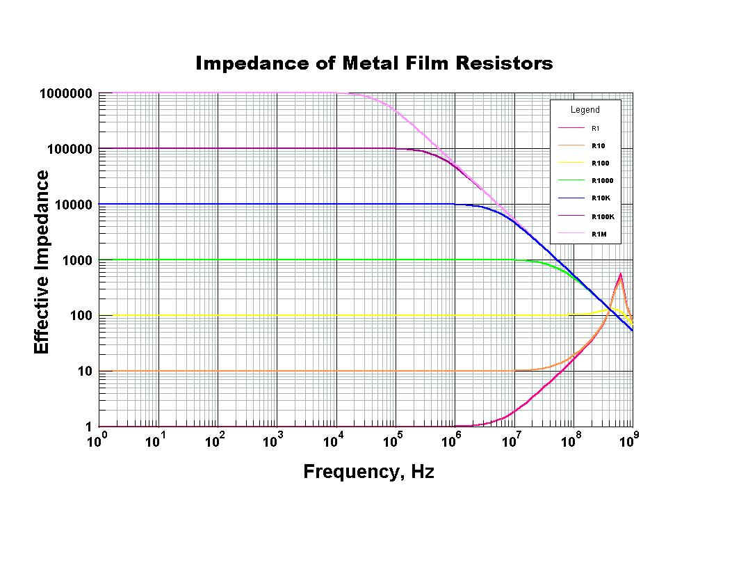
resistance value and see how much difference it makes. With a 100 ohm
resistor at 1 MHz, the effective impedance is SQRT(100^2 + 6^2) or
about 100.18 ohms - not very much difference. As the resistance
increases, the effect of a little inductance gets even smaller.
In fact, the biggest reactance seen with resistors, be they carbon
composition or film resistors, is parallel capacitance. The end caps
of a resistor are typically a few millimeters apart. This produces
some capacitive effects alone. The conformal coating on film resistors
increases this somewhat. The thicker encapsulation on carbon
composition resistors produces even higher capacitance. Without going
into details on how this capacitance can be estimated, allow me to
just say the typical 1/4 to 1/2 watt resistor typically has about 2 to
5 picoFarads of shunt capacitance across the resistance. At a given
frequency, you can calculate the effect this extra capacitance has on
the effective impedance of the resistor. Basically, it become worse
as you increase the frequency, but it is rarely a problem until you
have very high resistance at VHF and higher frequencies.
Barry L. Ornitz (c) 1997
Since this was written, I have received questions about the noise
performance of various resistors. Carbon composition resistors are
generally considered the worst since their resistivity depends a lot on
the contact resistance of individual granules of graphite. This contact
resistance changes greatly with temperature, mechanical vibration, and
especially humidity. As I mentioned earlier, carbon composition resistors
tend to increase in value as they age (sometimes going as high as several
times their original value). This is mainly due to the loss of proper
contact between the granules.
Carbon film resistors have much better noise characteristics than do the
carbon composition units. They should maintain this property as they age,
but I expect that their noise will increase with time. Since carbon film
resistors are the low-end replacement for carbon composition units, this
is to be expected. Carbon film resistors do suffer thermal overload much
quicker than carbon composition units because of their lower thermal mass.
The lowest noise film resistors are the metal and metal oxide film types.
These tend to remain stable over long periods of time, and most can handle
short-term overloads quite well.
When repairing older equipment, it is usually a very good idea to inspect all
resistors for signs of damage. Cracked phenolic cases, or charred spots on the
case are a dead giveaway that the resistor needs to be replaced. However,
I have seen many carbon composition resistors drastically increase in value with
no external visible evidence of damage. It is worth measuring the resistance
of all resistors when restoring very old equipment.
As I mentioned earlier, the maximum voltage rating of most modern resistors is
around 350 volts. In actuality, this was the case years ago but most equipment
designers knew the phenolic cased resistors could usually withstand much more
voltage than this. A few paid the price, however, like Heathkit who replaced
many CRT’s in their color TV kits when 19 cent resistors failed by having over
1000 volts across them. Today’s resistors are generally smaller than those of
yesteryear, so if you need a higher voltage rating, use additional resistors in
series.
Barry WA4VZQ ornitz@usa.net (c) 1998
|
To answer the question about how much inductance can be found in
a spiral cut metal film resistor, I calculated the inductance for
a ribbon coil which would be the same dimensions as the film on a
1/4 watt film resistor. These calculations were based on:
5 complete turns for the winding
Length = 0.15 inches
Diameter = 0.07 inches
Winding Pitch = 0.03 inches
Strip Width = 0.025 inches
Coating Thickness = 0.001 inches
To calculate the inductance, I used equations for "Helices of
Rectangular Strip" from:
Grover, F. W.: "Inductance Calculations", Instrument Society
of America, 1946, ISBN 0-87664-557-0, pp. 164-166.
The equations present a correction term to the equivalent
cylindrical current sheet inductance. The correction for edge
insulation is based on geometric mean differences for rectangles.
In addition to solving some monstrous equations, the solution
required several one dimensional and one two dimensional cubic
spline interpolation of tabular data.
I obtained the following results:
Sheet Inductance = 36.36 nH
Correction = -13.40 nH
Inductance = 22.96 nH
We can compare this result to that given by traditional formulas
for solenoid coils:
ARRL Equation = 16.87 nH (ARRL Handbook)
Nagaoka's Equation = 16.98 nH (Radiotron Designers
Handbook)
The increase in inductance is due to the width of the strips
produced by the spiral trimming of the resistor.
To model this resistor, we place this inductance in series with
the resistance. We also need to add the shunting capacitance of
the ceramic body and the conformal insulation. This is typically
about 2 to 3 picofarads.
We can also include the inductance of the resistor leads using an
equation by Rosa.
Rosa, E. B.:"Bureau of Standards Paper", 169, 1912.
For 1/4 inch leads on each end, this adds (for non-magnetic leads
of 0.6 mm in diameter) an added inductance of 2.92 nH on each
end.
The equivalent circuit for this 1/4 watt resistor (forgiving the
crude ASCII representation) I came up with is:
Resistance
----UUUU--+-/\/\/\/\-+--UUUU----
3 nH | | 3 nH
+----|(----+
2.5 pF
If you calculate the impedance of this equivalent circuit, you
will find that the capacitive reactance dominates the response
for resistor values over approximately 100 ohms. For resistances
below 100 ohms, the inductive effect dominates.
To get an idea of how good this film resistor behaves over a
frequency range, the following table gives the approximate
frequency for which the resistance increases or decreases by 10
percent over its DC value.
Resistance, Ohms Frequency for 10%
Change in Resistance
1 3 MHz increase
10 30 MHz increase
100 300 MHz increase
1000 30 MHz decrease
10K 3 MHz decrease
100K 300 KHz decrease
1Meg 30 KHz decrease
My conclusion is that for resistor values over 100 ohms, film
resistors can replace carbon composition units with no worries.
The inductance from the spiral design is just not significant
unless you go to very low resistor values.
[Copyright 2002 B. L. Ornitz] All Rights Reserved
(check to enlarge this Resistor Graph) |
Transformer Ratings
Copyright 1999 B. L. Ornitz
A number of methods of "guestimating" transformer ratings have
been published. Most methods do quite well for large
transformers, but fail to give reasonable numbers for small
transformers. This is because small transformers have a much
greater core loss than do large transformers. Small transformers
are better able to dissipate heat than are large transformers,
so they are often designed with higher flux densities (and
higher core losses) - in an effort to save weight and cost.
Also, in small transformers, wire gauge cannot be used to
estimate the ratings as values from 200 to 1500 circular mils
per amp ratings are in use.
For large transformers in commercial service, a 40 C temperature
rise is the norm (40 C or 72 F temperature rise over room
temperature). It is best to keep transformer temperatures low;
90 C or 194 F should be an absolute maximum unless you know the
transformer has insulating materials that can withstand higher
temperatures. [But if you know this for sure, why are you
bothering to estimate the ratings?] Experimental evidence has
shown that transformers generally deteriorate twice as fast for
every 8 C (12 F) rise in temperature. So keep the transformer
as cool as possible (a reason why I always use solid state
rectifiers instead of tubes, reducing the transformer load by
eliminating the rectifier filament power). A good rule of thumb
is to operate the transformer for several minutes at the
expected load. If you can hold your hand on it without it being
too hot to touch (about 60 C or 140 F), the transformer is
adequate for that load. Watch out for high voltage, however.
For amateur use, a typical transformer can be used to supply
higher levels of power than in commercial service because of the
intermittent current demand. In powering single sideband
transmitters, even higher power levels can be obtained; while
the peak power may be high, the average power may be quite low.
With the above information in mind, the following equations
should make some sense. While we are talking power here, we
should actually use volt-ampere units rather than watts since
the transformer generates heat with both real and reactive
power.
-----
Commercial Service (also use for receivers):
Average Volt-Amperes = 1.4 * Transformer Volume (in cubic
inches)
Average Volt-Amperes = 28 * Transformer Weight (pounds) -
100
Thus a 10 pound transformer would be rated for 180 volt-amperes.
Such a transformer would be about 5 inches on a side. A potted
military transformer might be somewhat larger and heavier than
this for the same rating. The potting adds weight but only
causes a slight improvement in cooling.
-----
CW Service:
Average Volt-Amperes = 60 * Transformer Weight (pounds) -
250
-----
SSB Service:
Average Volt-Amperes = 70 * Transformer Weight (pounds) -
250
So the same transformer as above would be rated for 350 V-A for
CW and 450 V-A for SSB service, while only 180 V-A for
continuous duty. It is easy to see why SSB allowed weight
reduction in military gear.
For small transformers, as noted earlier, higher core losses can
be tolerated. If you can measure the effective core area, a
better estimate can be obtained. With typical E I laminated
cores, measure the cross sectional area of the center of the
"E". Then use the following equation. This is good for small
transformers up to about 500 volt-amperes. Note the area is
raised to the 1.5 power.
Average Volt-Amperes = 40 * Area (sq.in.) ^ 1.5
Thus a transformer having laminations 1.75 inches thick with the
width of the E being 1.5 inches would have an effective area of
2.625 square inches. This would give an estimate of 170 watts
for this transformer.
The ultimate test of a transformer’s ratings, as mentioned
earlier, is determined by its temperature rise. If, after a
while of operation, the transformer is not too hot to touch, you
are operating it at a safe level. If you need just a little
more power from the transformer, provide for better cooling.
This may be nothing more than providing better ventilation
around the transformer, or it may mean a small fan is needed.
Very old transformers, with insulating materials not rated for
today’s standards, need to be run cooler than modern
transformers. Reducing the load on old transformers can also
prolong their life, so consider using solid-state rectification.
If you decide to operate at a higher transformer temperature,
do so with caution and knowledge that you are reducing its life.
It should be noted that the replacement of solid-state
rectifiers for vacuum diodes will result in a higher voltage
output from the power supply. Thus a resistor may be needed in
series with the diode to maintain the same final voltage. This
resistor will generate heat, of course. But it will generate no
more heat than the original tube did. In fact, it will generate
less heat as the filament power is not being used. Placement of
this resistor may be important for adequate cooling so remember
this when substituting silicon diodes for tube rectifiers. With
typical rectifier tubes, the transformer will see from 10 to 15
watts less heat it has to dissipate when going to silicon
diodes.
Chokes
For chokes, some other considerations are in order. Chokes
typically have an air gap to reduce core saturation. Thus they
should be operated at current levels where their inductance is
still adequate for the filtering they perform. Higher currents
lead to saturation and a decrease in inductance. Wire resistance
is an issue too since with excessive resistance, the voltage drop
may be high. Even if the voltage drop is tolerable, and the
inductance is still adequate, the choke must also be able to
dissipate the heat produced by core losses and its resistance.
As in transformers, limiting the temperature rise is a good way
of preventing damage to chokes. The same as with transformers,
a 40 C (72 F) temperature rise is the normal maximum. The old
rule of thumb follows with chokes too. If you can safely hold
your hand on the unit after several minutes of operation, the
choke is not operating at too high a temperature. Again, watch
out for high voltage.
Barry L. Ornitz, PhD WA4VZQ [Copyright 2002 B. L.
Ornitz]
|
|