|
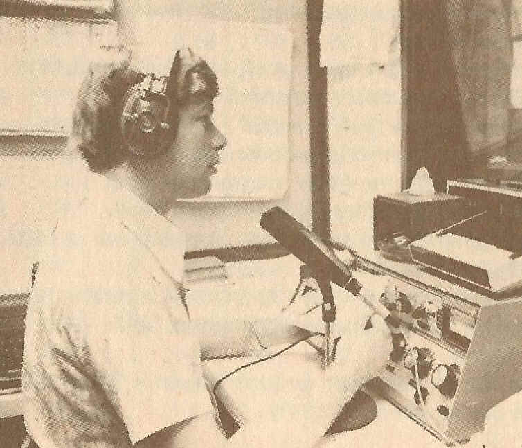
From the 1981 KOY Almanac By Ed Phillips, and when Ed changed employment, later to be published by KTAR. This was page 40. We have this AVQ-10 Radar The word radar means Radio Detection And Ranging. Simply put, a radar is a device used to detect distant objects that reflect radio energy. Since only objects that reflect energy show up on the radar screen, they are called "echoes." In the case of a weather radar, the energy is reflected because of precipitation, not clouds, aircraft or dust. This feature enables the user to 'see' within the clouds and find out if they are producing rain or snow. The rain and snow echoes are displayed on a screen much like a T.V. picture. From the location on the screen, the operator can determine the direction and distance the rain is away from the radar unit. The KOY Weather Station is equipped with weather radar. An RCA AVQ-10 Aircraft Radar has been modified for stationary operation. With our radar, the strongest storms can be seen 150 nautical miles away. The distance you can see rain is of course limited by mountains and buildings because the radar signal travels in a straight line. Our radar set also has a fifty mile range. We use it most often because it gives good coverage to all of the Salt River Valley. A 20 mile range is also available to use when storms are in close range. We operate our radar any time rain is threatening the valley. KOY is the only broadcasting station in the valley that has weather radar. Radar updates are given every half hour during morning and afternoon drive times when there is rain around. If severe weather threatens, you can count on us to have the storms pinpointed and keep you abreast of the latest weather developments. 40 |
|||||
|
------------------------------------------------------- ---------------------------------------------------------------------------------------------
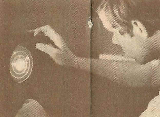
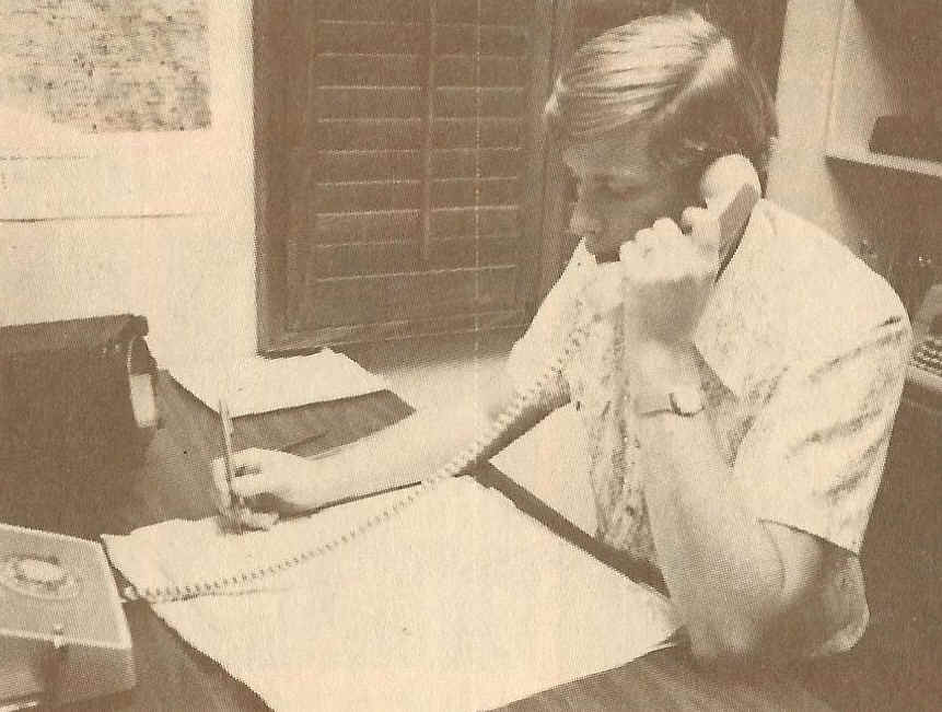
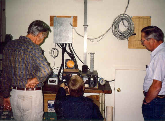
(These 3 photos are from the 1980 version of the KOY Ed Phillips Almanac they are different than those in the 1981 version and special as it shows the radar screen in 2 of them! see more at http://www.smecc.org/6BBH_-_KDYM_-_KFCB_-_KOY_-_history.htm ) |
|||||
|
C
BAND AIRBORNE SEARCH.
|
|||||
|
WEATHER RADAR AVQ-10 Complete AVQ-10 system, showing receiver-transmitter unit, antenna, control panel, accessory unit and two indicators.WHAT IT IS . . . The AVQ-10 is a lightweight airborne radar, designed specifically to meet the exacting requirements of airline and executive transport operators. WHAT IT DOES. . . The AVQ-10 can "see' storms and show nonturbulent paths through or around them. This feature of highly accurate "in flight" weather reconnaissance permits pilots to navigate between storm cores and around turbulent areas, ,enabling operators to maintain flight schedules and provide smoother rides for their passengers. The AVQ-10 also provides for terrain mapping by adequately identifying land and water masses and detecting mountains. means ECONOMY OF OPERATION Installation of AVQ-10 will greatly improve operational economy by permitting closer adherence to schedules and minimizing long detours or flight cancellations. PASSENGER COMFORT There is nothing more disturbing to an airline customer than passage through turbulent areas. These areas, which sometimes cause extremely rough riding, not only induce air sickness, but may inconvenience passengers to the extent of possibly discouraging future air travel. The AVQ-10 will enable planes to avoid most turbulent areas, thus providing a smoother ride and, subsequently, greater peace of mind for passengers.
ARRIVAL TIME DEPENDABILITY By avoiding turnbacks and extensive detours, planes will be able to arrive more frequently on schedule. This improvement of arrivaltime dependability will gain passenger confidence.
REDUCTION OF PILOT FATIGUE Pilots have long been plagued by the uncertainty and unpredictability of weather conditions while in flight. The inadequate storm warning facilities of any meteorological system and the constantly changing turbul,ent conditions aloft require untiring visual vigilance on the part of these pilots. This constant state of tension can result in excessive fatigue. The use of the AVQ-I0, especially on extended flights under IFR conditions, will reduce the strain on pilot reflexes by providing better-than-sight interpretation of weather conditions and provides these features
ISO ECHO CONTOUR FEATURE Accurate interpretation of scope information can be acquired by pilots with a minimum amount of training. Analyzing the degree of turbulence displayed in a PPI picture has been simplified by the use of ISO Echo Contour principles. Generally, the brighter the intensity of display the more dense the rainfall. The PPI, however, can only display a certain degree of intensity; consequently, progressively heavier rainfall areas will appear uniform on the display, which is not a true picture. The ISO Echo Contour circuit provides for a black picture to appear on the PPI when the signal return intensity reaches a preset level. The black areas on the scope then represent the storm cores, the areas of greatest moisture density. By avoiding these blacked out areas, the pilot can avoid the areas of greatest turbulence. LIGHTWEIGHT CONSTRUCTION Weight factors were given prime consideration in the design of the AVQ-I0. As a result, substantial weight reductions were made without any loss of quality, operating capability or penetration A complete AVQ-10 system, including all units (less shock mounts), weighs less than 125 pounds.
BRIGHT DISPLAY INDICATOR The AVQ-10 has been constructed so that an indicator unit using a display storage tube can be substituted for the standard indicator. The bright display tube allows the pilot to read scope information without the use of a hood under bright light conditions. In this way, the pilot can read the radar indicator as he would the flight instruments.
GENERAL Radar System Complement - 5 major units (6 with two indicator operation)Overall Weight-not installed - Approximately 125 Ibs.Multiple Indicator Operation - Maximum of two Indicators may be usedBright Display Indicator - The system is designed so that the Bright Display Indicator may be substituted for the standard indicator without changes to the equipment or aircraft wiringPrimary Power 600 VA of 115 volts AC ± 5'10, 380 to 420 cycles 375 VA of 115 volts AC ± 10'10,380 to 420 cycles 30 watts of 27.5 volts DC Operating Frequency-5400 mcs ± 30 mcs Ranges-20-50-150 nautical miles Altitude - Antenna--45,000 ft.; all other units 16,000 ft.Temp. Range - Antenna-40° C to +70° C; all other units -40° C to +55° CGyro Information
RECEIVER· TRANSMITTER Size-One ATR Weight-43.75Ibs. Mounting-Shock mounted plug-in unit with "quick-disconnect" Waveguide connector Power Output-75 KW peak Pulse Width - 2.0 microsecondsRepetition Rate - 400 cycles (synchronized with line frequency)Magnetron Operation Time Delay - 5 minutesACCESSORY UNIT Size - One ATRWeight - 33 Ibs.Mounting - Shock mounted plug-in unitRange Marks - 5, 10, 25 mile spacing.ISO-Contour Separation - Adjustable over range of 5 db to 20 db
ANTENNA Reflector Size - 22", 30", and 34"Weight - 25 lbs.Mounting - Unshockmounted plug-in unit with "quick-disconnect" provisions for waveguide and power connectorsScan Rate - 15 rpmType Scan - 360° continuousType Stabilization - Line-of-SightAntenna Pattern - 7° horizontal beamwidth with 22" reflectorPolarization - Fixed horizontalTilt - Up 10° down 15°Stabilization Accuracy - ±2° (under conditions of 0° manual tilt) during pitch and roll of aircraft, up to ±20° total excursion (for roll rates up to 20°/sec).
INDICATOR UNIT Size - 61/4" sq. front with %" radius corners x 13112"Weight - 13 lbs.Mounting - Shock mountedPPI Tube - 5" diameterControls - The following controls are provided on the front of the Indicator: CURSOR, INTENSITY, LIGHTS and RANGEMARKS
BRIGHT DISPLAY INDICATOR UNIT Size - 6 1/4" square front with 3/4" radius corners x 14112"Weight - 15 lbsMounting - Instrument panel, shock mountedPPI Tube - 5" DiameterControls - INTENSITY, RANGE MARKS, ERASE RATE, and variable polaroid filter
CONTROL PANEL Size - 33/8"x5%"x4112" Weight - 2 lbs Mounting - Unshockmounted plug-in unit Controls - The following controls are provided for selection of all system functions: OFF - STANDBY - RANGE - switch, TILT control. GAIN control, CONTOUR control, and STABILIZATION IN-OUT control Edge Lighting - Edge Lighting is provided for night time use. (A kit of pa,rts is available for custom construction of control panels)
|
|||||
|
(From: THE DISPLAY OF WEATHER ECHOES ON 5.5 cm AIRBORNE RADAR UAL METEOROLOGY CIRCULAR No. 39 UNITED AIR LINES INC. DENVER, COLORADO March 15, 1956 Henry T Harrison, Superintendent of Weather Service Flight Operations Department.)
|
|||||
|
THE DISPLAY OF WEATHER ECHOES ON THE 5.5 cm AIRBORNE RADAR 1. INTRODUCTION This Circular presents additional meteorological results of three years of flying tests and ground studies of the prototype and pre-production model 5.5 cm airborne weather mapping radar built for United Air Lines by Radio Corporation of America under specifications laid down by the Air Transport Association and by Aeronautical Radio, Inc. While the original UAL report in 1954* covered the general results of the 1953 flying tests, this present report will discuss the nature and significance of weather echoes in greater detail. The pictures were selected from the UAL file of four radar catalogs which now contains more than 8,000 radar scope photographs - all fully identified and correlated with the associated weather situation. Source of Data While written primarily for meteorologists, the material in this report should prove useful as a detailed reference source for flight personnel and flight dispatchers as well, to supplement the radar course and training literature received by them from the Denver Flight Training Center. It would be well for the reader to bear in mind that all of the pictures described herein were taken at flight altitudes which ranged from 500 feet above the ground up to a maximum of 15,500 feet msl, or were actually taken while the radar was operating on the ground at Denver. Since uptilt was used on the radar antenna in nearly all cases, it is believed that the diagnosis of each echo should be valid for other airborne radars operating at flight levels up to about 20,000 feet. Above this level, and certainly above 25,000 feet, it is possible that the significance of the storm echoes will have to be reappraised in a year or two in the light of subsequent experience with the radar at higher levels. A separate section will be included on this point near the end of the report. Comparison With Other Radars The analysis of the C-band radar echoes will not necessarily be valid for the same echoes dis *''Evaluation of C-Band (5.5cm) Airborne Weather Radar." 1954. UAL publication. played on radars operating on the 3.2 cm band (X) , the 10 cm band (S) or the 23 cm band (L); in fact, it is certain that they will not be comparable in many instances because of the inherent differences of each band with respect to attenuation, resolution, and sensitivity characteristics. More and more we are beginning to realize that the diagnosis of a particular radar weather echo ,is dependent to a very great extent upon the type of the radar producing the picture. Even assuming that each radar operator tunes his antenna-gain-brilliance controls for optimum performance, there are still three factors which must be considered in all cases before the real meaning of the radar observation can be determined. These factors are: 1. Wave length of reporting radar. 3. Power output. Since RAREPS distributed over the various teletype circuits may originate from almost any type of radar from .8 cm up to 23 cm in wave length, using antennas varying from about 18 inches up to more than 30 feet in diameter, or with power outputs varying more than tenfold, flight operations personnel in the field are sometimes faced with a confusing problem in trying to interpret the reports. The .8 cm radar, described somewhat facetiously 'as being capable of "seeing your breath," is nearly useless under rain conditions. Certain powerful 3.2 cm radars such as the Air Force CPS-9 are known to be capable of painting echoes on fair weather cumulus clouds, but suffer attenuation and distortion of picture when penetrating heavy rain. * Powerful 10 cm sets, using antennas six feet or more in diameter, produce a sharp picture with minimum of attenuation even under excessive rainfall rates, but they are obviously unsuited for airborne application because of the power and antenna requirements. Theory and actual tests demonstrated that the six-centimeter band offered the most prac *''The Use of Radar in Weather Forecasting With Particular Reference to Radar Set AN/CPS-9." MIT Technical Report No. 20. By Hal Foster. 1952. 2 Weather Echoes on 5.5cm Airborne Radartical compromise for obtaining maximum sensitivity with minimum attenuation of signal in an airborne set. It was because of these considerations that 5.5 cm was adopted as the optimum operating wave length for airline airborne equipment by the Air Transport Association and Aeronautical Radio, Inc. Pre-Production Model Display vs. the Production Model DisplayAll pictures contained in this report were taken of the original prototype 5.5 cm set built for United by RCA in 1953 and as modified several times during the three years of testing operations by UAL electronic technicians Frank Todd and David Clark. It is already apparent to everyone who has worked with the new production model that the picture on the field radar is perceptibly sharper, the contour display is superior, and the range of reception of all echoes is greater. The first new set installed in the MAINLINER "O'Connor" picked up several thunderstorm echoes on the outer range mark of the 150-mile range during one of the Denver Flight Training Center Project flights to Redwood Falls, Minnesota, on July 7, 1955. The improved picture is the result of engineering refinements built into the new set by RCA engineers working closely with United's own electronic technicians. Another difference to keep in mind is that the line radar scope will have the writing beam centered 25 % below the geometrical center of the scope. This point was adopted after several experiments as the most practical compromise in giving the pilot maximum blowup of the picture ahead of him with minimum loss of picture to the right and left of the plane. How To Read The Scope Photographs 1. In the aerial pictures, 12 o'clock is always straight ahead of the plane. Heading is indicated by the compass figure (magnetic) in the slot at the edge of the scope at 11 o'clock. 2. In the ground pictures taken in the airplane, the direction the plane is facing is also indicated by the compass figure in the slot at 11 o'clock.3. In the ground pictures taken with the radar in the final roof position at the Operating Base, the scope is map reading with true north at 12 o'clock and east at 3 o'clock. 4. The effective sweep of the scanner is limited to about 2400 in all pictures taken while the set was installed in the airplane.5. A full 3600 scope picture appears in all photo graphs taken with the radar on the roof installation.6. Date and flight number appear in the lower left. 7. Range marks may be identified by the number which appears on the scope. 5 marks visible signify 2-mile intervals, 6 marks are 5-mile intervals and 4 marks are 25-mile intervals.8. Since the scope was photographed in a mirror, the clock prints as an inverted mirror image. 9. All radar photographs were taken with a PERISCOPE, RECORDING CAMERA (TYPE 0-5) TYPE A-1, SERIAL 275 SPECIFICATION NO. R-31409, ST. GEORGE RECORDING EQUIPMENT CORPORATION, NEW YORK CITY.
|
|||||
| (There are many many pages of photographs of the scope face showing formations these are not present here on this web page.) | |||||
|
94 Weather Echoes on 5.5cm Airborne RadarAPPENDIX A BRIEF HISTORY OF THE DEVELOPMENT OF AIRBORNE WEATHER RADAR Note (Much of the material contained in this abbreviated history was presented as part of the third annual report of the AT A Meteorological Subcommttee to the Operations Conference at WiIIiamsburg, Virginia, on June 15, 1955. The special committee charged with preparing this report consisted of H. T. Harrison of UAL (Chairman), R. H. Curtis of CAL and J. A. Browne of TWA. Presentation was made by Harrison.) WORLD WAR II To pick up the thread of the airborne weather radar story, it is well to recall that the display of weather echoes grew up quite accidentally as an unintentional by-product of military radars which were designed for bombing and navigation purposes near the start of World War II. When it was discovered that radar could see water drops about as well as it picked up ground targets, meteorologists were quick to recognize the enormous potentials of this new instrument as a weather observing and forecasting tool. Almost overnight, we were in the fortunate position of being able to X-ray thunderstorms, hurricanes and general storm areas to complete the third dimension picture which had been missing up to that time. EARLY TWA RESEARCH Near the end of World War II, considerable interest was focused on the possibility of installing cockpit radar in airline planes for storm avoidance purposes. Trans World Airlines in late 1945 and 1946 had a close look at a 3.2 cm airborne set which was built especially for them by Bell Laboratories and Western Electric from components taken from war surplus equipment used by the military. Subjected first to a series of tests on the ground in the TWA Weather Office at Kansas City for three months, the radar was then installed in a C-47 plane for a series of flight checks. While the immediate results of this project were somewhat disappointing, the TWA group under Ralph Ayres was enthusiastic over the possibilities and recommended that future airborne search radars should be developed specifically for storm avoidance. J. A. Browne, Manager of Meteorology for TWA, took an active part in all of the ground tests and some of the flight research. AAl PROJECT American Airlines, operating under a Navy contract, was another pioneering airline to conduct a major project looking into the application of airborne radar. The American group did some excellent work in correlating 3.2 cm radar pictures with I FR penetrations of actual thunderstorm conditions, including the development of a highly practical application of the principle of providing a second rainfall rate contour for the purpose of painting in the heavy rain cores of storms. This attachment was first known as ISOECHO CONTOUR CIRCUITRY, but has gradually been shortened to the simple term CONTOUR. Among those participating in this project were: Don Beard, A. F. Mereweather Superintendent of Weather Services for American, Frank White- (now with ATA), and Sam Saint who is now with ANDB after a tour of duty with AT A. This project was also credited with developing the principle of correlating heavy thunderstorm turbulence with sharp edged radar echoes, possibly the greatest contribution of all in the developmental history of airborne weather avoidance radar. NAVY PROJECT The Navy conducted another airborne radar project in 1949 and 1950 with one of the main purposes being to determine the possibility of identifying hail shafts on the 3.2 cm radar. Commander Earl Perce and Lt. Montgomery were the pilots and Frank White again took part in this project as radar officer, this time on active duty as a Navy Reservist. Joe George, Superintendent of Meteorology for Eastern, served on this project as Weather Observer while on active duty as a Brigadier General in the Air Force Reserve. Winding up in Denver during June 1950, the ruggedness of these tests is shown by the fact that hai I damage to the plane was severe enough to force cancellation of further flight testing. WEAKNESSES OF WARTIME EQUIPMENT In spite of the early post-war enthusiasm, it soon became evident that there was a major obstacle standing in the way of immediate adoption of airborne radar by the airlines. This was the unsatisfactory nature of the available equipment which had been built for military use and primarily for purposes other than storm avoidance. The equipment was heavy, it was subject to frequent breakdowns and - because it operated on a wave length of 3.2 cm - it produced seriously distorted pictures whenever the beam penetrated heavy rain or whenever the plane was flying in heavy rain. In short, the 3.2 cm radar was a useful piece of equipment for detouring storm areas, but appeared to be undependable for penetrating corridors in lines of thunderstorms on the airway. Appendix 95ATA-ARINC SPECIFICATIONS It was not until May 1, 1952, that ATA came face to face with the problem by taking positive steps to break the bottleneck. On that historic date, a group of interested ATA members drew up a set of ten operational requirements which was then submitted to the Airlines Electronic Engineering Committee under the chairmanship of Frank Todd of United with orders to convert the requirements into technical characteristics. The most critical of these requirements was the one pertaining to attenuation of the radar by heavy rain: "3. The equipment must be capable of penetrating and displaying at short range rainfall rates of 60 mm/hr to a depth of 15 miles." THE McGill STUDY This ATA-ARINC requirement practically ruled out consideration of 3.2 cm as the wave length for the standard airline radar in the United States by virtue of its well known attenuation characteristics at lesser rainfall rates. To make doubly certain on this point, however, AT A and ARINC contracted with McGill University to carry out a theoretical study to find the most practical wave length for airline radar, keeping in mind the limitations imposed on the equipment by the size of the antenna dish and the available power supply in the typical modern transport plane. The McGill study, produced by J. S. Marshall and Walter Hitschfeld, contained the following conclusion: "That an operating wave length of 5.5 cm will provide optimum performance for weather mapping radar from the standpoint of providing maximum sensitivity with minimum attenuation of signal in heavy rain." FIRST PROTOTYPE TO AIRLINE SPECIFICATIONS - THE UAL PROJECT Shortly after the AEEC specifications were announced, one manufacturer - Radio Corporation of America - contracted with United to build a prototype radar to meet all of the airline specifications. Delivered in Denver June 1, 1953, this completely new C-Band radar was subjected to a series of 40 flight tests by United in thunderstorm conditions over the Western Plains during the summer of 1953 with the results being reported in the UAL publication, "Evaluation of C-Band (5.5cm) Airborne Weather Radar." When these tests demonstrated that the prototype radar met all of the AEEC specifications satisfactorily, the United evaluation team recommended that the company purchase this type of radar for fleet installation. FIRST PRODUCTION 5.5 CM MODELS Two manufacturers - RCA and Bendix - submitted pre-production 5.5 cm airborne radars to United ,in January and February of 1955 for bench testing by the Communications and Engineering Departments in Denver and San Francisco respectively. These tests culminated in the placing of an order by United with RCA on 4/5/55 to equip the entire UAL fleet with C-Band radar. All UAL Convairs will be operational by the spring of 1956, all DC-6's and DC-7's by the fall of 1957. As of the present writing, practically every airline in the country has placed orders for airborne radar with a majority calling for C-Band equipment. A third manufacturer, Collins Radio, has recently entered the airborne radar production field with a 5.5 cm radar built to ATA-ARINC specifications. ADDITIONAL UAL GROUND TESTS Pending delivery of the final production models, ground observations were continued by United on the original prototype set at Denver starting in the spring of 1954 with the radar still installed in the DC-3 airplane. In September 1954 the set was transferred to a permanent location in the Weather Office at the Operating Base with the transmitter/receiver and power units being installed in an aluminum house on the roof and the antenna shielded by a masonite radome immediately above. Observations have been almost daily with the set ever since, including pictures of the scope whenever interesting weather developments took place. The original prototype was replaced with a production model RCA AVQ-10 5.5 cm radar in October 1955. The United catalog now includes pictures of wet snow, dry snow, steady rain, rain and snow showers, hail, thunderstorms, terrain and anomalous terrain echoes. It also includes a number of radar pictures taken of thunderstorms where small tornadoes were reported by ground observers, but these pictures have shown little in the way of a useful correlation to identify the tornado on the scope. (More on this subject in Section 7 of this report.) There are now more than 400 pictures of hail shafts which started with the 23 flights in 1953 where hail was known to have occurred, followed by ground observations of hail shafts on 8 days in 1954 and 11 days in 1955. All pictures are fully identified and are available quickly for study and reference by any interested persons.96 Weather Echoes on 5.5cm Airborne Radar APPENDIX II COMPARISON OF SPECIFICATIONS OF ORIGINAL RCA PROTOTYPE AND THE 1955 PRODUCTION 5.5 CM RADAR |
|||||
| Specification | Prototype 1953 | AVQ- 10 1955 | |||
| Operating wave length | 5.5 cm | 5.5 cm | |||
| Antenna diameter | Antenna diameter22" parabola | 22" or 30" ellipse | |||
| Beam width | 7.5 | 5.4 with 30" dish | |||
| Rate of scan | 15 or 40 rpm | 15 rpm | |||
| Antenna tilt | -150 to +90 | -150 to +100 | |||
| Antenna stabilization | Roll | Roll and pitch | |||
| Scan | 3600 continuous | 3600 continuous | |||
| Power output | 53 kw | 75 kw | |||
| Indicator scope | Center PPI | 25% off-center PPI | |||
| Scope brightness | Viewing hood | Viewing hood | |||
| Scope ranges | Scope ranges10 - 30 - 100 | 20 - 50 - 150 | |||
| Range marks | 2 - 5 - 25 | 2 - 5 - 25 | |||
| PPI tube diameter | 5"5" | 5"5" | |||
| Over-all weight | 200 pounds | 116 pounds | |||
| Iso-contour attachment | Yes | Yes | |||
| Iso-contour ratio | 5 to 20 db | 5 to 15 db | |||
| Circular polarization | Yes | No | |||
| Sensitivity time control | Yes | Yes | |||
| Magnetron warm-up period | 8 minutes | 4 minutes | |||
|
APPENDIX III BIBLIOGRAPHY OF UAL RADAR PUBLICATIONS AND TRAINING AIDS Films "The Adventures of Sir Echo." 1953. A 50-minute documentary moving picture of the radar flight tests of 1953 in 16 mm color. Produced by M. E. Balzer. Radar echoes and cloud exteriors are shown side by side with running sound commentary by Balzer. "United's New look." 1955. A 40-minute pilot training moving picture in 16 mm color produced by Thomas J. Barbre Motion Picture Productions of Denver under the technical direction of M. E. Balzer and F. J. Todd. Motion picture sequences are shown of the actual scope in operation on board the Mainliner O/CONNOR while approaching and penetrating thunderstorm conditions. Running sound commentary by Balzer. Copyright UAL. "UAL Training Film No. 1." 1955. A 10-minute supplementary training moving picture designed for use as a final examination of pilots at end of training course. 16 mm block and white. Silent. Copyright UAL.
Other Classroom Aids Classroom Slides. 72 Vu-Graph transparencies of radar scope pictures. Developed by M. E. Balzer. 10-inch size. Complete with lecture outline and notes. Copyright UAL. Radar Home Study lesson For Pilots. 1955. Section of revised UAL Home Study Course in Meteorology. Prepared by M. E. Balzer and H. R. Hoffman. Copyright UAL. UAL Radar Catalog. 1953- 1956. Four volumes containing approximately 8/000 glossy prints of scope pictures correlated with associated weather conditions. Original film negatives and 35 mm slides also available.
Technical Papers "The Operational Applications of Airborne Radar." 1954. By E. A. Post. "Application of Airborne Radar To Airline Operations." 1954. By E. A. Post. "Airborne Weather Radar Evaluation." 1954. UAL COCKPIT. 9-54. By E. A. Post. "The History of Modern Airline Radar - Its Development, Performance/ Application, and Installation." 1954. By F. J. Todd. "The Display of Hail Echoes on 5.5 em Weather Mapping Radar." 1956. By H. T. Harrison. 20 illustrations.
Book-length Reports "Evaluation of C-Band (5.5 cm) Airborne Weather Radar." 1954. By H. T. Harrison and E. A. Post. Official UAL report on results of 40 flight tests in 1953 using the RCA prototype radar. 108 pages. Illustrated. "The Display of Weather Echoes On The 5.5 cm Airborne Radar." 1956. UAL Meteorology Circular No. 39 by H. T. Harrison. 250 illustrations.
|
|||||
|
RCA AVQ-10 Weather Radar Movie |
|||||
| RCA AVQ-10 Weather Radar Movie
|
Be sure that you have allowed active content when this web page loaded to watch the movie! | ||||
|
|
|||||
 RADIO CORPORATION OF AMERICA AVQ-10
Ad from 1958 RCA Electronic Age Magazine
RADIO CORPORATION OF AMERICA AVQ-10
Ad from 1958 RCA Electronic Age Magazine
RCA ELECTRONICS KEEPS A RADAR "WEATHER EYE" ON YOUR COMFORT ON THE GREAT AIRLINES Airlines equipped with RCA all weather radar include: United Air Lines (DC-7 above), Trans-World Airlines, American Airlines, Continental Airlines, Pan American, Braniff, CAA, Air France, Cia Mexicana, Swissair, Sabena, BOAC. Iberia, RAAF, Air India, Qantas, Cubana, Karhumaki, Real-Aerovias, TCA, Japan Air Lines, Panair Do Brasil, Swedish Nabel Beard, Pakistan Airlines, SAS, Thai Airways Ltd., Ethiopian Airlines, Olympic Airlines. Flying into a starless night, the pilot's vision may reach a mere 50 yards. Yet he sees a storm brewing 150 miles ahead. Within minutes he plots a slight change in course and has a smooth, safe corridor through the weather. His passengers complete their trip in comfort and on schedule. Credit RCA Electronics for the "Weather Eye" radar that makes all this possible. And United Air Lines' all-radar Fleet for being first (among 24 leading airlines) to use this important development. RCA has also produced radar to guide ships at sea, and track man-made satellites through space. RCA pioneered and developed color TV, produced the world's largest electronic computer, peanut-sized transistors and much, much more. Progress like this helps explain why RCA means electronics and why electronics means a happier, healthier, more secure future for you. |
|||||
|
From the 1981 KOY Almanac By Ed Phillips, and when Ed changed employment, later to be published by KTAR. This was page 40. We have this AVQ-10 Radar The word radar means Radio Detection And Ranging. Simply put, a radar is a device used to detect distant objects that reflect radio energy. Since only objects that reflect energy show up on the radar screen, they are called "echoes." In the case of a weather radar, the energy is reflected because of precipitation, not clouds, aircraft or dust. This feature enables the user to 'see' within the clouds and find out if they are producing rain or snow. The rain and snow echoes are displayed on a screen much like a T.V. picture. From the location on the screen, the operator can determine the direction and distance the rain is away from the radar unit. The KOY Weather Station is equipped with weather radar. An RCA AVQ-10 Aircraft Radar has been modified for stationary operation. With our radar, the strongest storms can be seen 150 nautical miles away. The distance you can see rain is of course limited by mountains and buildings because the radar signal travels in a straight line. Our radar set also has a fifty mile range. We use it most often because it gives good coverage to all of the Salt River Valley. A 20 mile range is also available to use when storms are in close range. We operate our radar any time rain is threatening the valley. KOY is the only broadcasting station in the valley that has weather radar. Radar updates are given every half hour during morning and afternoon drive times when there is rain around. If severe weather threatens, you can count on us to have the storms pinpointed and keep you abreast of the latest weather developments. 40 |
|||||
 Radar
Sees The Weather
Radar
Sees The Weather