RCA TELEPRINTER SERVICE - Error Correcting and ARQ-M
+ Anything else related to RCA Teleprinter systems
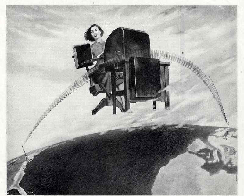 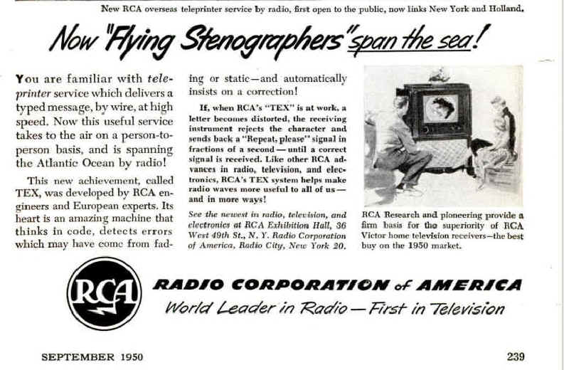
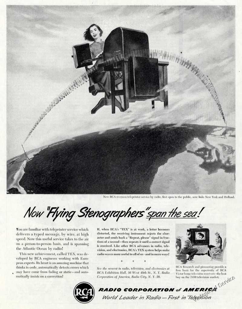
, Popular Mechanics, September 1950, page 239.
|
||||||||||||||||||||||||||||||||||||||||||||||||||||||||||||||||||||||||||||||||||||||||||||||||||||||||||||||||||||||||||||||||||||||||||||||||||||||||||||||||||||||||||||||||||||||||||||||||||||||||||||||||||||||||||||||||||||||||||||||||||||||||||||||||||||||||||||||||||||||||||||||||||||||||||||||||||||||||||||||||||||
| Back in the 1930s
John Moore of RCA Communications devised a teleprinter code using a 3-out-of-7 bit selection, permitting error detection. Later on there was developed a system for automatically requesting retransmission of errored material. John B. Moore "Constant-Ratio Code and Automatic-RQ on Transoceanic HF Radio Services." IRE Transactions on Communications Systems, March 1960, p. 72. The system has some similarities to present-day AMTOR-SITOR Several years ago there was on ebay a tape punch like the Teletype GPE but punched 7-level code and had an RCA nameplate on it. Reasonable guess that Teletype made them for RCA and that it punched Moore code. jhhaynes |
||||||||||||||||||||||||||||||||||||||||||||||||||||||||||||||||||||||||||||||||||||||||||||||||||||||||||||||||||||||||||||||||||||||||||||||||||||||||||||||||||||||||||||||||||||||||||||||||||||||||||||||||||||||||||||||||||||||||||||||||||||||||||||||||||||||||||||||||||||||||||||||||||||||||||||||||||||||||||||||||||||
ARQ-M
From Wikipedia, the free encyclopedia ARQ-M,
short for Automatic
Repeat reQuest, Multiplex, is a radio telegraphy protocol
used to reliably forward telex messages
over partially reliable radio links.[1] It
is a low-speed system designed to match the performance of landline
telex systems and allow those messages to be forwarded over long
distances using shortwave radios.
The first ARQ-M link was built in the Netherlands, and began
exchanging messages with a counterpart in New York in 1947. ARQ-M is similar in concept to ARQ-E, but ARQ-E has no multiplex
capability and uses a different 7 bit alphabet. History[edit]
The telex system, which developed out
of the telegraph system, is based on defined electrical current levels
that are interpreted as a mark or space signal. These are normally
send over well-defined networks with considerable infrastructure that
keeps error rates very low. In contrast, radio communications are
subject to a wide variety of noises and other signal problems that
leads to losses. To forward telex messages successfully over radio
links, some form of error
correction should
be applied. ARQ-M was developed to automatically
deal with errors.[2]The automatic repeat request system was invented by Hendrik van Duuren of
the Netherlands in the 1940s[2] and
so it became known as the van Duuren automatic error correction
system.[3] The
seven unit code used was called the van Duuren code. ARQ was first used commercially in
1947 with a link from Amsterdam to New York with the master station in
Amsterdam.[4][1] In
May 1950 the TEX (Overseas teleprinter exchange) service between New
York and Amsterdam started. TEX was an early name for TELEX which is a
system to allow automatic routing of private messages from a sender to
a receiver on the TELEX network. Prior to the introduction or ARQ-M
there were so many errors in the messages received that staff from the
telecommunications companies had to manually check messages and
conform correct receipt. Once ARQ-M was introduced, messages could be
automatically and reliably sent over long distances via shortwave
radio, and so was introduced into automatic systems.[1][5] By
1956 ARQ radio circuits were running from New York to Amsterdam,
Berne, Brussels, Frankfurt, London, Paramaribo,
Paris, Rome, and Wien, with plans for Copenhagen, Lisbon, Madrid, and
Oslo. Amsterdam had radio links to Berne, Curaçao, Jakarta,
Paramaribo and Rome. Brussels linked toLeopoldville. Frankfurt was connected to Madrid and Rome with
plans for Buenos Aires. A link from Madrid to Canary Islands was
planned.[6] By
1959 most radio circuits for Telex were using ARQ.[1] International
shortwave ARQ data links have been replaced by undersea cables and
satellite circuits.[5] The New Zealand Post Office used
a two channel multiplex ARQ system to communicate on two circuits
between Wellington and Vancouver and Sydney over shortwave radio for a
few years till 1961.[7] The
radio link was available for 22 or 23 hours a day, and could improve
the error rate from 1% to 0.001%.[8] In
1961 the radio system became a backup for the primary COMPAC undersea
cable,[9] with
telegraph operations conducted using voice frequency telegraphy over
telephone channels instead.[10] The Department of Transport in
Australia used to run several multiplexed ARQ data links to remote
airports prior to the use of AUSSAT.[11] These
were calls the aeronautical fixed teletype network. It was used to
communicate aeronautical and meteorological data.[11] A
station at Perth, VZPH and VKP communicated with Cocos Island VZCC,
Port Headland VZPD, Darwin VZPM, and Sydney VZSY.[11] The
station in Sydney communicated with Alice Springs, VZAS, Mount Isa,
VZMA, Norfolk Island VZNF, and Lord Howe Island, VZLH. International
radioteletype links connected Sydney (as VLS3) to Singapore on 9ME and
Jakarta 8BB.[11] Radio Corporation of America, who were
the first in USA to use ARQ-M, named their ARQ equipment
"automatic error reduction and correction equipment".[12] By 1990 use of ARQ-M had reduced.
However it was still used by French
Forces to
communicate between Paris, and N'Djamena, Djibouti, Port
de France, Papeete, Dakar, Port-Bouët, Le Port, Reunion. One link ran between Companhia Portuguesa Radio Marconi in
Lisbon and the Vatican.
The British Royal Army, Navy and Air force still used it from England
and Gibraltar. Moscow had a link with Kabul, Havana and Hanoi. ASECNA had
a network of west African airports. Moroni in
the Comoros has a link to Paris, Stockholm had a link to Ho Chi Minh
City, and Brussels had a link to Kinshasa. Canadian armed
forces used shortwave radio as satellite links into the Arctic are
difficult. Martin-de-Viviès, and Port-aux-Français connected
back to France for Direction des Telecommunications des Reseaux
Exterieurs.[13] On 17 November 2005 the European
patent office rejected an appeal about overturned patent number
0309763 from NEC which attempted to patent a mutiplexing system, after
they agreed that it did not add anything new beyond European patent
0099101 A and the Siemens Elmux 1000.[14] Description[edit]
Basic
details[edit]
ARQ-M is a duplex radio
communications protocol used to ensure that data is transmitted
correctly over a partially unreliable radio path.[15] Data is encoded using 7 unit binary
codes sent
using a seven bit error detecting code
called van Duuren code or CCITT Telegraph Alphabet No. 3. The data is
sent in two channels labelled A and B, or four channels labeled A, B,
C and D. Data from the different channels are interleaved using a time division multiplex system.
The two channel system is called ARQ-M2,
the four channel system is called ARQ-M4.[15] In order to synchronise to the synchronous data stream
the encoded characters can be sent erect or inverted. Inverted means
that the 0 and 1 are swapped, whereas erect means that the character
is sent without modification. There are two possible channel
arrangements depending on the latency of the circuit. For normal
latency the cycle consists of four characters, and if the channel has
extra long latency it has eight characters. Channel A (or C) has one
character inverted followed by either three or seven erect characters.
Channel B (or D) has one character erect followed by either three or
seven inverted characters.[15] Transmission
rates[edit]
There are several standard
transmission rates. The preferred standard rates are 96 baud for
the two channel system and 192 baud for the four channel system.
These rates allowed running at the same speed as 50 baud Telex
landline systems. The transmission cycle was 145 5⁄6 ms
long. Another standard rate allowed interoperation with 45 baud
networks, with a repetition cycle lasting 163 1⁄3 ms and baud rates of 85 5⁄7 and 171 3⁄7 for
the two and four channel systems. The fastest standard speed used 100
and 200 baud, with a transmission cycle of 140 ms and was
incompatible with land based networks, but more commonly used for
point to point links.[16] Performance[edit]
Two performance measures give quality
characteristics of an ARQ-M link. These are error rate and throughput.
Residual errors can be due to transpositions of the symbol elements or
double errors. The chances that this happens is about 100 to 1000
times less than for a working unprotected link. A log graph of
residual error rate against raw error rate shows a steeper line with
slope 2 intercepting at 100% errors. If the unprotected 5 unit code
had an error rate of 1%, the ARQ-M protected code error rate is
0.0025%.[17] Throughput is reduced by errors. If
the raw error rate increases to 3% the link will be blocked all the
time with retransmissions. Each transmitted cycle of 28 bits has a
likely chance of an error in these conditions. An eight character
repeat cycle has twice the impact. At 1% raw errors the throughput for
the 4 character cycle system is about 80%. On real equipment, an
efficiency meter may indicate how good the throughput is.[17] Alphabet[edit]
The alphabet used in the ARQ-M
protocol is based on the CCITT Telegraph Alphabet No. 2 more
commonly known as Baudot.[18] This
alphabet has five bits, and therefore has 25 or
32 different possible symbols. It uses letters shift and figures
shifts to select different sets of characters similar to a typewriter.
The ARQ-M alphabet being synchronous always has to send data and does
not have gaps between characters. It does not include start and stop
bits that would be used in asynchronous transmissions and so saves on
those two bits per character. In asynchronous transmissions a steady
stop signal indicates that there is nothing to send. A prolonged start
signal can be used for signalling, for example to select a destination
for a telex connection. The ARQ-M characters are remapped to a
seven bit system so that there are always three bits on and four bits
off. The ARQ code is a Moore code, which can detect the
modification of any single bit.[19] This
alphabet is CCITT
Telegraph Alphabet No. 3 This
differs from the alphabet used in the ARQ-E single
channel system.[18] Three
additional control signals are added to the 32 from the Baudot set.
Out of 128 seven bit characters there are 35 that have three one bits
set, so allowing for the 32 Baudot and three control codes to just be
accommodated. The extra control characters are RQ, meaning request
repeat, α meaning constant space condition, which may indicate
the end of a connection (break signal) or be used to signal
information, such as a number to connect to, and the β character,
meaning constant mark condition, used when there is nothing to send.
The RQ signal is also called Signal Roman one and may be designated
"I". The number of one bits is checked by
the receiver to tell if an error has occurred in the transmission of
the character. There should be three ones in each character received.
The return channel will include the RQ signal if an error is detected.[18]
ltrs is
the symbol to activate the letters shift. figs is
the symbol to activate figures shift. Space is
equivalent to the space bar cr is carriage
return lf is line
feed cells with blank entries are undefined
for international communications, but may have meaning within one
country. The code was invented by Hendrick van
Duuren during world war II, and so has been called van
Duuren code.[20][21] Marking[edit]
Seven bit characters have the
alternative to be sent erect, meaning that 0 stays as 0 and 1 stays as
1, or inverted where each 0 changes to 1 and 1 changes to 0. The
standard specifies a marking pattern which says which characters are
erect and which are inverted in a particular pattern, that enables the
system phase, channel and subchannel to be determined. Since the
system is synchronous there is no start bit, and a receiver has to
examine the bit stream to tell where the start of a marked cycle is.
When system phase is established the correct received bit can be
assigned to the correct place in each character in each channel. The
receiver can determine that system phase is established as each
character will contain three one bits and four zero bits. In
recommendation 342-2 here are two different marking lengths schemes.
For the four character repetition cycle, Channel A is encoded
↓↑↑↑ (4333) and channel B is marked
↑↓↓↓ (3444). These are combined in a time
division multiplex method with characters in the order A1 B4 A2 B1 A3
B2 A4 B3 resulting in a marking pattern
↓↓↑↑↑↓↑↓ (44333434 one
bits) to match the first character from channel A at the start.[16] For the eight character repetition
cycle, Channel A is encoded
↓↑↑↑↑↑↑↑ (43333333)
and channel B is marked
↑↓↓↓↓↓↓↓ (34444444).
The combination marking pattern
↓↓↑↑↑↓↑↓↑↓↑↓↑↓↑↓
(4433343434343434 one bits).[16] In
practice the eight character repetition cycle has not been observed in
use on the airwaves.[22] In a four channel system, channel C is
encoded the same way as channel B, and channel D the same as for
channel A.[16] Bits
for channel C are interleaved with channel A and those for D
interleaved with channel B. Elements of A come before C, and B come
before D.[16] In CCIR recommendation 242 the marking
is much simpler with the A channel erect and the B channel inverted.[23] Subchannels[edit]
Each of the two or four channels has
the option to be split into four subchannels so that more streams of
data can be sent, but at lower rates. These subchannels are numbered 1
to 4. The subchannel numbered 1 is identified by being the character
that has the different polarity from the others in the stream. So the
subchannels will be arranged like this in the multiplex 4CRC stream
where italic means inverted:[15] A1 B4 A2
B1 A3 B2 A4 B3 If a data stream that is half rate is
required, then subchannels 1 and 3, or 2 and 4 are combined. A three
quarter rate subchannel can be made by combining subchannels 2, 3 and
4.[15] If
one half-rate and two quarter rates are required the half-rate gets
subchannels 2 and 4. The facility to split the channel is called a
channel divider. It would provide a stop signal during the time when a
sub-rate user is not receiving a character.[24] Costs
for such a circuit were lower than for a full rate.[24] The
marking system used enables the receiver to determine the subchannel
order.[24] In practice use of subchannels has not
been observed although international partial rate fixed services were
once available.[22] System
setup[edit]
In order to have a functioning system,
a circuit has to be set up consisting of two transmissions in both
directions. One station will be the master, and the other will be the
slave station. The slave station will determine its timing from the
master station. The first stage is automatic phasing,
also called phase hunting, where each end will determine the correct
phase of the character stream. During this stage a receiver will slip
a bit until system phase is achieved and the system phase matches the
marking pattern. The slave station is supposed to send seven bits
0000000 or 1111111 in place of the signal repetition. Once synchronisation is achieved data
can be transferred. The mark signal will be sent to the connected
equipment so signal that the circuit is available. As characters are
received at one end they will be inverted according to the marking
pattern and checked for the present of three 1 (mark) symbols. If it
is an error, a RQ character is sent on the return path. No characters
are sent on from the receiver for a period of four character times. If
an RQ character is received, then the transmitter will start a BQ-cycle
in response, send an RQ character and repeat the last three characters
sent. This phase of operation is called cycling as the same four
characters will be recycled. Hopefully the receiver will have good
reception of these and then forward them. If not the RQ will re sent
again and repetition attempted.[5] Standards[edit]
ARQ-M is recommended by CCIR 342-2
(now called ITU-R F.342-2) and earlier CCIR 242. ARQ-M was standardised by the Comité consultatif international pour
la radio. The XII Plenary session in New Delhi in 1970
approved recommendation 342-2 Automatic
error-correcting system for telegraph signals transmitted over radio
circuits.[16] The CCITT produced
recommendation S.13 [25] Use on radio circuits of 7-unit synchronous systems giving error correction
by automatic repetition.[26] The earlier Recommendation 242 is not
compatible with F.342-2.[27] This
had an equivalent CCIT document approved in 1956 at Geneva C.24. Alternative names for ARQ-M are TDM, TDM-242, TDM-342 or 96-TDM.
ARQ-M2 is also known as TDM-2,
or ARQ-28, and
the ARQ-M4 variant is known as TDM-4,
or ARQ-56.[28][29] Equipment[edit]
Companies that manufactured equipment
for this system were found in Germany, Japan, Netherlands,
Switzerland, and USA.[1] The
companies include RCA,[1] the
Marconi HU121, and the Electra Mux. Hasler from
Berne in Switzerland made a four channel TOR (Telex on Radio) system.[30][31] RCA called
their equipment RCA Electronic Multiplex.[32] Siemens
AG made an
ARQ terminal in 1956 called Multiplex-Funkfernschreibanlage MUX 4D 7a,[33] and
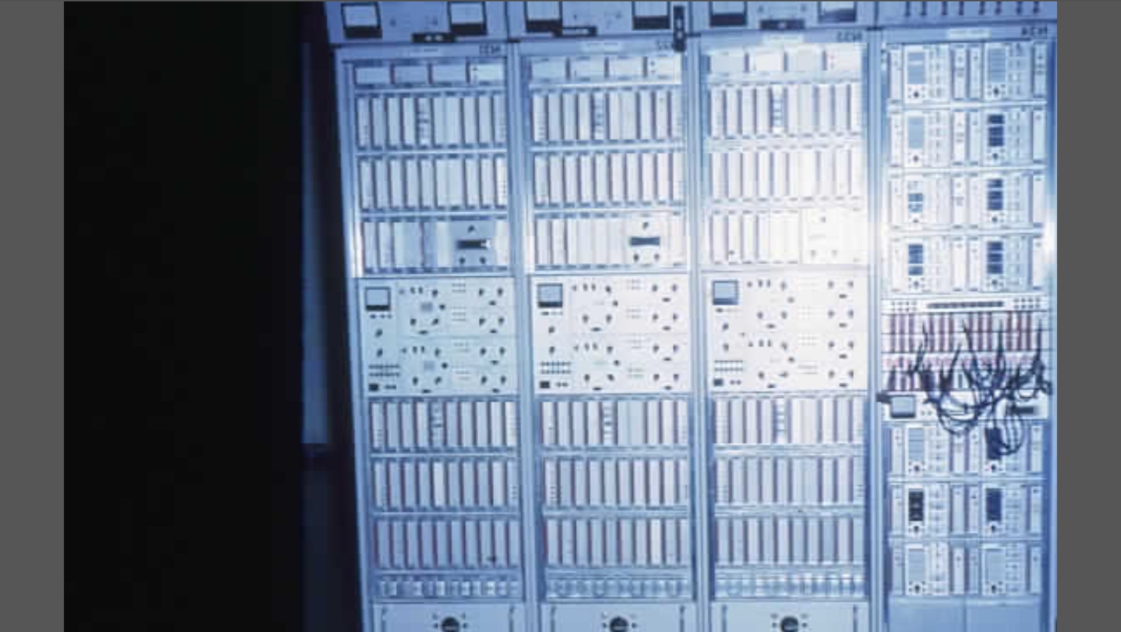
later a two channel ARQ terminal called the Elmux 1000.[5][34] The equipment for the ARQ-M systems
contained a receive side and a transmit side. Each channel also had
supporting circuitry for channel A and B, and C and D if present. Each
subchannel also had supporting circuitry controlled by a channel
divider. The channel divider has output control
lines for each subchannel A1 A2 A3 A4 B1 ... for both receive and
transmit sides. The signals from the divider outputs are combined with
and-gates in the subchannel circuitry. Each subchannel on the send
section side includes a serial to parallel converter, and a tripping
pulse that clocks in the next character. On the receive section side
and output buffer is driven by the and-gate that picks the channel
receive character selected by the channel divider signal at the
appropriate time.[5] On the send section the channel
circuit includes a delay line feeding a repetition storage. The common
send section circuit includes a code translator that changes the five
bit code to the seven bit code. Next the seven bit character goes to
an output shift
register, and then to a polarity inverter. For a four
channel system the bits would then be interleaved between AB and CD
channels. The final send step is a tone modulator and output circuit.[5] The
tone is modulated using frequency shift keying. The 0 (or space)
signal picks out a lower frequency, and the 1 ( or mark signal) picks
out a higher frequency. This signal to frequency conversion may be
inverted, and this is common below 10 MHz. On the receive section the signal from
the radio receiver comes to a tone demodulator, then a polarity
inverter, and then to an error checking circuit, and at the same time
to an input shift register that converts from serial to parallel. Next
it goes to a code translator to convert from seven bits to five bits.
From here the five bit code goes to a parallel to serial converter,
controlled by a repetition cycle timer on the receive side.[5] Interoperation[edit]
Because the telex network does not
give feedback to a sender about when a message is delivered, and a shortwave ARQ
link may or may not be available, systems with ARQ links set them up
to be store and forward half duplex systems. This means that a telex
sender transmits their telegram in
full to the message centre that then stores and forwards the message
over the shortwave link when it is available. Call charges were
calculated for the time when the link was running without errors,
either at six or ten second increments.[5]CCITT recommended not charging if reliability was below 80%, and to give a
busy signal if reliability was not satisfactory.[35] Signalling is needed to determine the
start and end of a call, and the destination of the connection. Two
systems have been used, signalling system B CCITT U1 and CCITT U20. An international telex exchange
would have signalling conversion facilities.[5] Monitoring[edit]
For radio spectrum monitors, ARQ-M is
classified as a digital mode, and radio stations that use
it will be termed utility
stations. Two stations communicating with ARQ-M will use
two different frequencies as data is continuously transmitted in each
direction. Channels are often running in idle mode and have a rhythmic
sound, as the symbol pattern repeats every 7/12 second.
A fax machine running
at 240 lines per minute can record the overall pattern of symbols.
Such a chart will show 24 pulses on each line for a two channel
system, forming columns down the page. Timing is very accurate with
each symbol lasting the same time of 10.416666 ms. This is the
duration for 96 baud elements.[15] Software is available to receive and
decode utility transmissions that use ARQ-M including Go2MONITOR,[36][37][38] and
there is also hardware such as the Code300-A from Hoka Electronic,[39] and
Wavecom M 4010.[22][22] References[edit]
1.
^ a b c d e f Moore, J. (1960).
"Constant-Ratio Code and Automatic-RQ on Transoceanic HF Radio
Services". IEEE Transactions on Communications 8 (1): 72–75. doi:10.1109/TCOM.1960.1097598. ISSN 0090-6778. 2.
^ a b van Duuren, Hendrik
Cornelis Anthony (1941). Typedruktelegrafie op radioverbindingen.
Waltman. 3.
^ Croisdale, A.
(1961). "Error Rates and Error Detection on Telegraph
Circuits". IEEE Transactions on Communications 9 (1): 28–37. doi:10.1109/TCOM.1961.1097653. ISSN 0096-2244. 4.
^ Salem, Imene Ben. "Adaptation
des taux et des puissances de transmission pour les schémas
IncrementaI Redundancy HARQ tronqués". University of
Quebec. p. 5.
Retrieved 23 August 2014. 5.
^ a b c d e f g h i Wiesner, Lothar (1975). Telegraph and Data Transmission over
Shortwave Radio Links.
Berlin: Siemens Aktiengesellschaft. pp. 114–120. ISBN 3800912325. 6.
^ Hennig, F. (1956). "Funkfernschreiben mit selbsttatiger Fehlerkorrektur
(Radio telex with automatic error correction)". Z. Nachrichtentech (in German) 9: 341 –348.
Retrieved 23 August 2014. 7.
^ James, R. A. (15
January 1962). "Transmission of teleprinter signals on radio using
automatic error detection and correction". New Zealand Engineering (Wellington: New
Zealand Institution of Engineers) 17 (1): 22–26. ISSN 0028-808X. 8.
^ James, R. A. (15
April 1962). "Teleprinter Over Radio Equipment". New Zealand Engineering (Wellington: New
Zealand Institution of Engineers) 17 (4): 152. ISSN 0028-808X. 9.
^ Kuchen, J. O. (15
July 1962). "Exploitation for N.Z. Telephone Services". New Zealand Engineering (Wellington: New
Zealand Institution of Engineers) 17 (7): 262–265. ISSN 0028-808X. 10.
^ James, R. A. (15
July 1962). "Exploitation for N.Z. Telegraph Services". New Zealand Engineering (Wellington: New
Zealand Institution of Engineers) 17 (7): 265–267. ISSN 0028-808X. 11.
^ a b c d Lynn, B. L. (1980). "Radio Teletype Adaptive Control Unit (RTTAC) for
Control of Data Transmission over High Frequency Radio Links". Conference on Microprocessor Systems 1980:
Preprints of Papers.
Barton, ACT: Institution of Engineers, Australia. pp. 39–44.
Retrieved 19 August 2014. – via InformIT (subscription
required) 12.
^ Atkinson, Edward W.
(Summer 1965). "Dial 859 for Greenland International Telex Connects
Continents for Space-age Communications". Electronic Age: 16.
Retrieved 24 August 2014. 13.
^ Klingenfuss, Joerg
(1991). Klingenfuss Utility Guide 1991. Klingenfuss Publications. pp. 22–261. ISBN 3924509913. 14.
^ "T 0668/04 () of 17.11.2005". EPO. 17
November 2005.
Retrieved 19 August 2014. 15.
^ a b c d e f Joerg Klingenfuss
(1991). Radioteletype Code Manual (11 ed.). Tuebingen,
Germany: Joerg Klingenfuss Publications. pp. 67–69. ISBN 3924509115. 16.
^ a b c d e f The ITU
Radiocommunication Assembly (1970). "AUTOMATIC ERROR-CORRECTING SYSTEM FOR TELEGRAPH
SIGNALS TRANSMITTED OVER RADIO CIRCUITS". ITU. ITU.
Retrieved 18 August 2014. 17.
^ a b Wiesner, Lothar (1975). Telegraph and Data Transmission over
Shortwave Radio Links.
Berlin: Siemens Aktiengesellschaft. pp. 120–124. ISBN 3800912325. 18.
^ a b c d Wiesner, Lothar (1975). Telegraph and Data Transmission over
Shortwave Radio Links.
Berlin: Siemens Aktiengesellschaft. pp. 103–104. ISBN 3800912325. 19.
^ Reference Data for Radio Engineers (5 ed.). Howard W. Sams.
1966. pp. 30–46. ISBN 0672206781. 20.
^ Coulmas, Florian
(1983). Writing in Focus. Walter de Gruyter. p. 57. ISBN 9789027933591. 21.
^ Truxal, John G. (1990). The Age of Electronic Messages. MIT
Press. pp. 228–230. ISBN 9780262200745. 22.
^ a b c d "User Manual of the Wavecom M 4010 Data and Telegraph
Decoder". July 2003.
Retrieved 18 August 2014. 23.
^ Guillet, Francois
(2002). "RadioRaft - Multimode radio data decoder software -
Modes and options user's guide". RADIORAFT 3.21 RADIO SIGNAL DECODER SOFTWARE.
Retrieved 18 August 2014. 24.
^ a b c Wiesner, Lothar (1975). Telegraph and Data Transmission over
Shortwave Radio Links.
Berlin: Siemens Aktiengesellschaft. pp. 112–114. ISBN 3800912325. 25.
^ "Use
on radio circuits of 7-unit synchronous systems giving error
correction by automatic repetition". Blue Book.
Retrieved 20 August 2014. 26.
^ Wiesner, Lothar (1975). Telegraph and Data Transmission over
Shortwave Radio Links.
Berlin: Siemens Aktiengesellschaft. p. 108,157. ISBN 3800912325. 27.
^ CCIR (1959). CCIR Recommendation 242. Los Angeles: CCIR. 28.
^ Proesch, Roland
(2013-05). Technical
Handbook for Radio Monitoring Hf. Books on Demand. p. 148. ISBN 9783732241422.
Retrieved 17 August 2014. Check
date values in: 29.
^ Scalsky, Stan; Mike
Chace (2004). "Digital Signals FAQ Version: 5.3".
Worldwide Utility News. Retrieved 17 August 2014. 30.
^ Barker, Tom (September
2012). "Hasler mux TOR equipment image". OTVA Newsletter.
Retrieved 25 August 2014. 31.
^ ETH Zürich (1982). "Kurzwellenverbindungen im Satellitenzeitalter -
Vorlesung Krieg im Aether" (in German). p. 14.
Retrieved 25 August 2014. 32.
^ "Multiplex without Errors". The Science News-Letter (Society for Science
& the Public) 59 (12): 188. 24 March
1951.
Retrieved 29 August 2014. (subscription
required (help)). 33.
^ "Multiplex-Funkfernschreibanlage MUX 4D 7a" (in German). Siemens und
Halske Aktiengesellschaft. November 1955.
Retrieved 23 August 2014. 34.
^ Paetsch, W. (1971).
"Elmux 1000, ein neues ARQ-Multplexsystem Für Funkfernschreiben". Siemens-Zeitschrift 45: 123–129. 35.
^ ccitt (1972). "USE OF RADIOTELEGRAPH CIRCUITS WITH ARQ EQUIPMENT FOR
FULLY AUTOMATIC TELEX CALLS CHARGED ON THE BASIS OF ELAPSED TIME". CCITT standard U.23. Geneva.
Retrieved 20 August 2014. 36.
^ "go2MONITOR Tech specs". go2SIGNALS:.
Retrieved 17 August 2014. 37.
^ Van Horn, Larry
(April 2013). "What's
New". Monitoring
times:
59. 38.
^ "ARQ-M2-242". go2MONITOR 2.0 Technical Reference /
Standard Decoders HF. Retrieved 18 August 2014. 39.
^ "Code 200-A".
Retrieved 18 August 2014.
|
||||||||||||||||||||||||||||||||||||||||||||||||||||||||||||||||||||||||||||||||||||||||||||||||||||||||||||||||||||||||||||||||||||||||||||||||||||||||||||||||||||||||||||||||||||||||||||||||||||||||||||||||||||||||||||||||||||||||||||||||||||||||||||||||||||||||||||||||||||||||||||||||||||||||||||||||||||||||||||||||||||
| Back in the 1930s
John Moore of RCA Communications devised a teleprinter code using a 3-out-of-7 bit selection, permitting error detection. Later on there was developed a system for automatically requesting retransmission of errored material. John B. Moore "Constant-Ratio Code and Automatic-RQ on Transoceanic HF Radio Services." IRE Transactions on Communications Systems, March 1960, p. 72. The system has some similarities to present-day AMTOR-SITOR Several years ago there was on ebay a tape punch like the Teletype GPE but punched 7-level code and had an RCA nameplate on it. Reasonable guess that Teletype made them for RCA and that it punched Moore code. jhhaynes
|
||||||||||||||||||||||||||||||||||||||||||||||||||||||||||||||||||||||||||||||||||||||||||||||||||||||||||||||||||||||||||||||||||||||||||||||||||||||||||||||||||||||||||||||||||||||||||||||||||||||||||||||||||||||||||||||||||||||||||||||||||||||||||||||||||||||||||||||||||||||||||||||||||||||||||||||||||||||||||||||||||||
 |
||||||||||||||||||||||||||||||||||||||||||||||||||||||||||||||||||||||||||||||||||||||||||||||||||||||||||||||||||||||||||||||||||||||||||||||||||||||||||||||||||||||||||||||||||||||||||||||||||||||||||||||||||||||||||||||||||||||||||||||||||||||||||||||||||||||||||||||||||||||||||||||||||||||||||||||||||||||||||||||||||||
| Lester B Veenstra
Doug Jones Jim Haynes and Ed Sharpe contributed to this page. |
||||||||||||||||||||||||||||||||||||||||||||||||||||||||||||||||||||||||||||||||||||||||||||||||||||||||||||||||||||||||||||||||||||||||||||||||||||||||||||||||||||||||||||||||||||||||||||||||||||||||||||||||||||||||||||||||||||||||||||||||||||||||||||||||||||||||||||||||||||||||||||||||||||||||||||||||||||||||||||||||||||
