|
Vol. 21 September, 1922 No.3
RENSSELAER ENGINEERING AND SCIENCE RADIO EQUIPMENT RUSSELL SAGE LABORATORY SEPTEMBER 1922
Published Quarterly in March, June, September and December
at Entered January 20, 1902, at Troy, N. Y., as Second
Class Matter cover This from the SMECC archives. We have the original publication - photos here are small - COURSES OF INSTRUCTION CIVIL, MECHANICAL, ELECTRICAL AND
CHEMICAL
GENERAL INFORMATION-The Rensselaer Polytechnic Institute was established in Troy, N. Y., in 1824. It is the oldest school of engineering in America, and it is recognized all over the world as one of the foremost technical schools. Students have come to it from fifty-two of the states and territories of the Union and from thirty-seven foreign countries, including Argentina, Australia, Bahamas, Bolivia, Brazil, Canada, Chile, China, Columbia, Costa Rica, Cuba, Ecuador, Egypt, England, Germany, Guatemala, Haiti, Honduras, India, Ireland, Italy, Japan, Java, Mexico, Nicaragua, Panama, Peru, Romania, Russia, Salvador, San Domingo, Siam, Spain, Syria, Turkey, Uruguay, and Venezuela. The number of students is 1133.GRADUATE COURSES-Graduate courses leading to Masters' degrees in the five subdivisions given as undergraduate courses are provided. These are each one year in duration and lead to the degrees of M. C. E., M. M. E., M. E. E., M. Ch. E. and M. S. Graduate courses leading to the degrees Doctor of Science, Sc. D., Doctor of Philosophy, Ph. D., and Doctor of Engineering, D. Eng., are also given. UNDERGRADUATE COURSES-Five regular undergraduate courses, each four years in duration, leading to degrees, are given at the Institute. These are Civil Engineering, leading to the degree C. E.; Mechanical Engineering, leading to the degree M. E.; Electrical Engineering, leading to the degree E. E.; Chemical Engineering', leading to the degree Ch. E., and the course in General Science, leading to the degree B. S. PARTIAL COURSES-Beside the regular graduate and under, graduate course leading to degrees, various partial courses in science and engineering, not leading to degrees, are given. These may be selected from the subjects taught in any of the departments. They may be of any length. They may be taken by anyone who is qualified by previous preparation to intelligently understand the course he desires to select. CATALOGUES-Catalogues describing the various courses and giving requirements for admission will be sent upon application. 1
Rensselaer Polytechnic Institute RADIO EQUIPMENT General-The various systems of radio communication now in use are the practical outcome of that scientific research in physics, chemistry and mathematics, which characterizes present day civilization. It is the task of the engineer to apply the results of this research to the problems of our every day life, such as the rapid transmission of intelligence from one point to another Realizing its obligation to supply technically trained men for this work, the Rensselaer Polytechnic Institute has, from time to time, found it necessary to make additions to its radio laboratory equipment. The latest addition is a radio telephone broadcasting equipment of the best type known to the art, which has been installed on the third floor of the Russell Sage Laboratory. It was designed primarily to give practical instruction in the operation of apparatus, the theory of which is studied in the classroom. This equipment is due to the generosity of Washing A. Roebling, '57, John A. Roebling, '88, and the late Charles G. Roebling, '71. Popular interest in radio broadcasting has created a demand for diversified programs, and it is felt that engineering schools which require this type of apparatus for teaching purposes can assist in satisfying the demand of the public for broadcast entertainment by supplying programs of an educational nature. For this reason, this station, known by the call letters W H A Z, will broadcast every Monday evening at 8.15, Eastern Standard time, program. consisting of musical selections and addresses by men prominent in all fields of human activity. As there is a large amount of research yet to be done in the field of radio communication, this equipment will be used for the collection of data on fading, interference, etc., in long distance, short wave communication. Tests of this nature have already been made by this station for the United States Department of Commerce, 2
3
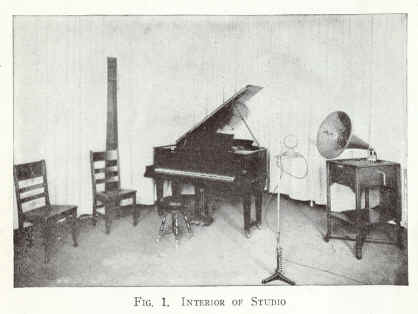
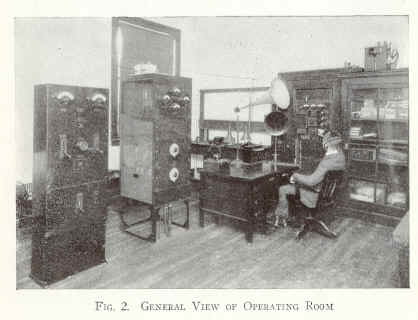
A short description of Station W H A Z follows- Studio-Figure 1 shows a corner of the studio. This room has received special acoustical treatment. The ceiling is covered with a thick layer of felt. One inch below this felt, suspended from the ceiling', is a perforated oil cloth covering. Sound waves passing through the holes in the oil cloth are quickly absorbed by the felt. The floor is covered with a heavily padded carpet. The treatment given the walls is somewhat different from that in the ordinary studio. The heavy curtains of friar cloth covering the walls are movable, thus permitting acoustical research and allowing the studio director a means of varying the amount of reverberation produced by the walls for different kinds of musical selections. A Steinway Duo-Art Reproducing piano and a Victrola are used for testing purposes. No mechanical instruments are used in the regular scheduled programs. In the center of the photograph (Fig. 1) is shown a sensitive microphone which is used to pick up the sounds produced in the studio and transform them into feeble electric currents which are carried by wires to the amplifier in the operating room (Fig. 2). ]'his microphone, mounted in a casing which minimizes the effect of mechanical vibration that might affect the clarity of the reproduced sounds, is designed to insure faithful reproduction of every gradation of tone of speech or music which is to be transmitted, and may be operated by talking close up or from a distance of several feet. Operating Room-Adjoining the studio is the operating room shown in Figures 2, 4 and 5. This room contains the transmitting, receiving and recording apparatus used in both radio telephony and radio telegraphy. This apparatus is described more in detail under separate headings. Speech Amplifier-Figure 2 shows a general view of the broadcasting section of the operating room. The wires from the microphone in the studio (Fig, 1) are connected to the speech amplifier which can be seen at the right of the operator's desk. This three stage amplifier increases the magnitude of the currents which it receives many thousand times and has been very carefully designed so that it can provide this tremendous increase of energy without any distortion of the original sound wave. The operator can manipulate this amplifier so that a proper amount of energy is produced no matter how loud or how soft the sounds in the studio may be. A loud speaker horn mounted next to the amplifier permits the operator to listen in while he is transmitting and thus determine the strength and quality of the signals sent to the radio transmitter. Radio Transmitter-The radio transmitter is shown in Figure 2 at the left hand side of the operator's desk. This transmitter is used 4 to produce high frequency electrical oscillations and vary their amplitude in accordance with the modulated current received from the speech amplifier. The system used is generally known as the Heising modulation system and is similar in principle to that used so successfully in the transmission system of our common battery telephone exchanges. The electrical energy from the speech amplifier is fed into the grid or input circuit of a 50 watt amplifier tube. The output circuit of this tube is connected through a transformer to the input circuit of two 250 watt tubes connected in parallel, which together act as a modulator of the high voltage, high frequency oscillations. Two other 250 watt tubes connected in parallel are used as the oscillator. The modulator and oscillator are connected in parallel and then through a choke coil across a 1600 volt, direct current, supply system. The operation is as follows: When the speech amplifier is sending no energy to the radio telephone transmitter, the direct Current divides equally between the plate circuits of the oscillator and modulator, and oscillations of a constant amplitude are produced. When the speech amplifier is operated, it changes the grid potential of the modulator tubes in accordance with the variations of the sound waves. The variations in the grid potential vary the direct current through the modulator, and since the choke coil in the direct current circuit makes it practically ca constant energy supply, the variations in the direct current supplied to the oscillator must be equal and opposite to the variations in the direct current supplied to the modulator. Since the amplitudes of the oscillations are proportional to the direct current received by the oscillator, it follows that these amplitudes must vary in accordance with the variations of the sound waves falling on the microphone in the studio. Four ammeters mounted on the face of the transmitter panel indicate to the operator the value of the current in the various circuits. Two control knobs just below the meters enable him to control the frequency of the oscillations and the amount of power radiated. Under normal operating conditions the high frequency power in the antenna circuit is about 500 watts. The wave length is measured by the Kolster wave meter which is visible on the left hand side of the desk (Fig. 2). At the present time Station W H A Z uses a 400 meter wave for broadcasting its regular programs. Power Supply-The power is supplied to the radio transmitter by a motor generator set. The driving motor is a 5 1/2 H.P. 110 volt direct current machine, direct connected to two direct current generators, one a 16 volt machine used to supply the filament current and the other a 1600 volt machine used to supply the plate current. 5
FIG. 3. EXTERIOR VIEW OF RUSSELL SAGE LABORATORY, SHOWING ANTENNA 6
Power Control--This motor generator set is controlled at the panel shown at the extreme left of Figure 2. A remote control automatic motor starter is actuated by means of a push button. The voltage of both generators, when once properly adjusted, is controlled by the motion of one knob. Monitoring System-On the right hand side of the operator's desk, (Figure 2) is shown a Western Electric receiving set, consisting of a detector and a two stage audio frequency amplifier. This is used with a loud speaker or telephone head set to enable the operator to listen in on the output of his transmitting set as it leaves the antenna. This receiver is automatically connected with the antenna when the transmitter is not in operation, and is then used to listen in on the programs of other stations and thus prevents unnecessary interference. Antenna System-The antenna, which is shown in Figure 3, is supported by two steel towers 80 feet high and 150 feet apart, placed on the roof of the Russell Sage Laboratory. This roof is 64 feet above ground level, is made of sheet copper and electrically connected at many points to the water pipes and steel frame of the building. The cross-arms or spreaders are made of galvanized iron pipe 18 feet long, guyed to the steel towers to prevent swaying in the wind. The antenna. is of the T type. The horizontal part consists of four stranded conductors 125 feet long. The lead-in wires are attached to the center point of the horizontal wires and come down in the shape of a fan to a point 30 feet below the horizontal wires where they arc formed into a cable. This cable is led into the operating room through a large porcelain bushing (Fig. 2) and ends on the center point of a single pole, double throw antenna switch. The ground connection is made from one pole of this switch to the water pipes, steel frame and roof of the building. From the other pole of this switch the antenna wire runs directly to the coupling coil of the radio transmitter, and then to the ground connection. The energy is transformed by this coil from the oscillator to the antenna circuit from which it is radiated into space. Radio Telegraph Transmitting Equipment-Other transmitters are employed for experimental and relay work using the call letters 2 X A P and 2 C D C. At the extreme left of Figure 4 is shown a 1 kilowatt spark transmitter using a 15,000 volt transformer and a nonsynchronous rotary gap. In the background of Figure 2 is shown a 100 watt continu0us wave telegraph set employing the Colpitt's circuit. This set may also be used as a 50 watt telephone transmitter for local work. It is supplied with 1000 volts direct current obtained by means of two Kenotron rectifiers from a 60 cycle alternating current line. The high power telephone set can be used as a continuous wave tele- 7 graph transmitter when necessary. Plans are now being perfected for the construction of a 1000 watt continuous wave transmitting set using the master oscillator circuit. This set will be used in transcontinental and transatlantic tests. Receiving Sets-Several different receiving sets arc in use at present. Figure 5 shows a second operator's desk with a Paragon receiver and a two stage amplifier. There is also a long wave receiving set and a 6 tube short wave receiver using three stages of radio frequency amplification. There is in course of construction an 11 tube superheterodyne receiver which will be used for Ion g distance tests. A western Electric "push and pull" amplifier is used wherever a portable amplifier is required. Short Wave Antenna-For 200 meter communication a 6 wire cage antenna is provided. This is 100 feet long and is almost vertical, being supported by the same towers which support the long wave antenna. Both antennae are usually left in place as they do not materially interfere with each other. Each tower is, however, provided with a set of pulleys and a windlass so that the entire antenna system can be changed in a few minutes when this is desired for special tests. Switching-In order to provide flexibility in operating the different sets, remote control switches mounted on the ceiling are so arranged that any receiving or transmitting set can be instantly connected to or disconnected from either of the antennae. All the transmitting sets are operated by the same transmitting key and the same remote control changeover switch. The receiving sets can be switched to a loud speaker located in any part of the building or to anyone of several recording devices. Recording Equipment-On the table at the left of the receiving desk in Figure 5 are shown two models of the Poulsen telegraphone. This is an old invention adapted to a new purpose. By means of this device, speech and music from a distant transmitting station are electromagnetically recorded on a spool containing six miles of fine steel wire. The record is then clearly reproduced as often as desired and erased at will. It can be amplified for reproduction in a loud speaker and could be rebroadcast by the radiophone if desired. The telegraphone is also used to record programs transmitted by VV H A Z or words spoken into the telegraphone itself. This instrument records radio telegraph signals and when these arc reproduced they offer an ideal opportunity for code practice as everything is recorded, including interference and static. The reproduction can be made faster or slower than the original. Experiments have been made with different methods 8
9
of operating relays by radio signals, and a device has been constructed for counting up the number of dots in the Arlington time signals and ringing a series of bells with the twelve o'clock dash. Historical Equipment-In the Electrical Engineering Laboratory are operating models of the various types of radio equipment used in the past. One of the original singing arc telephone sets, made by the DeForest Company, is shown on top of the apparatus case in Figure 2. I t is interesting to note that this small piece of apparatus performing, the same function as the modern broadcasting equipment shown in the same illustration. Next to it is an early Marconi, coherer type, radio telegraph receiver. In an adjoining room are two complete Telefunken radio transmitting and receiving sets. Future Development-The apparatus now installed, and under construction, in the radio section of the Electrical Engineering Laboratory, is the logical outcome of the most recent experimental and research work in radio engineering. As the field of radio communication develops, new devices will be added to keep the laboratory equipment a t the forefront of progress. 10
|
|