|
TELETYPE MODEL
31 - various variations!
Send in your SN# we are trying to determine how
many were made by number ranges... email info@smecc.org |
| We need parts to
support this unit! Please let us know of you have any model
31 spares, books drawings or stories! |
|
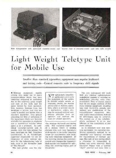
Light Weight Teletype Unit for
Mobile Use
Smaller than standard typewriter, equipment uses regular
keyboard and keying code—Control
converts code to frequency shift signals (TeleTech Feb 1947)
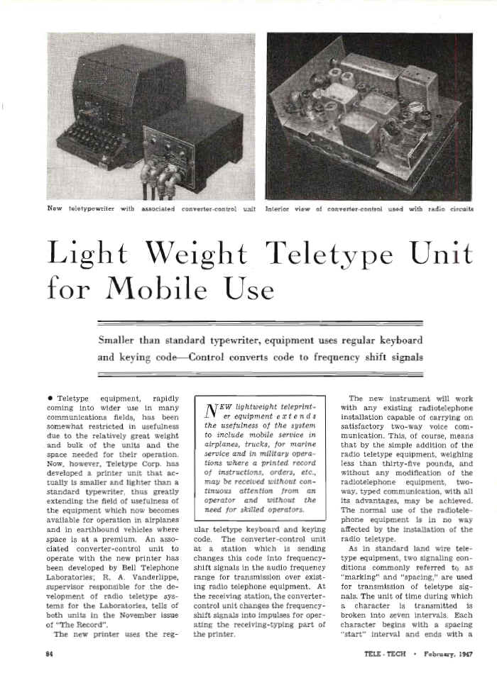
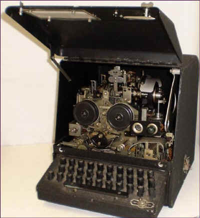
New
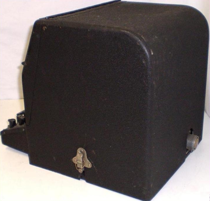
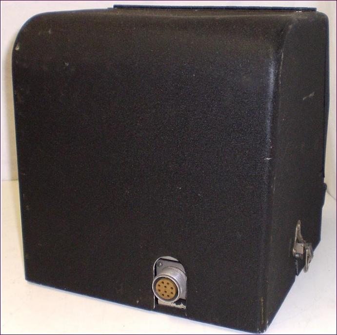
teletypewriter with associated converter-control unit Interior view of
converter-control used with radio circuits
|
Light Weight Teletype Unit
for Mobile Use
Smaller than standard typewriter, equipment uses regular keyboard
and keying code—Control converts code to frequency shift signals
• Teletype equipment, rapidly
coming into wider use in many
communications fields, has been
somewhat restricted in usefulness
due to the relatively great weight
and bulk of the units and the
space needed for their operation.
Now, however, Teletype Corp. has
developed a printer unit that actually
is smaller and lighter than a
standard typewriter, thus greatly
extending the field of usefulness of
the equipment which now becomes
available for operation in airplanes
and in earthbound vehicles where
space is at a premium. An associated
converter-control unit to
operate with the new printer has
been developed by Bell Telephone
Laboratories; R. A. Vanderlippe,
supervisor responsible for the development
of radio teletype systems
for the Laboratories, tells of
both units in the November issue
of "The Record".
The new printer uses the reg-
ular teletype keyboard and keying
code. The converter-control unit
at a station which is sending
changes this code into frequency shift
signals in the audio frequency
range for transmission over existing
radio telephone equipment. At
the receiving station, the converter control
unit changes the frequency shift
signals into impulses for operating
the receiving-typing part of
the printer.
The new instrument will work
with any existing radiotelephone
installation capable of carrying on
satisfactory two-way voice communication.
This, of course, means
that by the simple addition of the
radio teletype equipment, weighing
less than thirty-five pounds, and
without any modification of the
radiotelephone equipment, two-way,
typed communication, with all
its advantages, may be achieved.
The normal use of the radiotelephone
equipment is in no way
affected by the installation of the
radio teletype.
|
As in standard land wire teletype
equipment, two signaling conditions
commonly referred to as
"marking" and "spacing," are used
for transmission of teletype signals.
The unit of time during which
a character is transmitted is
broken into seven intervals. Each
character begins with a spacing
"start" interval and ends with a
marking "stop" interval. During
these intervals all printers which
are receiving are synchronized with
the printer which is sending.
During each of the five time intervals
between the start and stop
intervals, the signaling condition
may be either marking or spacing,
depending on the teletype character
being transmitted, so that
thirty-two different signaling combinations
are possible. By assigning
one combination for "upper
case" and one for "lower case," any
or all of the remaining thirty combinations
may be used for the
transmission of either of two characters
or symbols so that there are
enough combinations for all characters
and symbols on the keyboard
of the teletypewriter.
Frequency Shift
Circuits in the converter unit
provide an automatic closure to
condition the radiotelephone equipment
for transmission when the
first teletype character is sent. This
function is disabled when a message
is being received. Other control
circuits provide for holding the
selector magnet circuit of the teletype
printer in a marking condition
during idle periods of the circuit,
so that radio noise will not
cause false characters to be printed,
and to light lamps to indicate
whether the terminal is in a transmitting
or a receiving condition.
Openings and closures of the
printer transmitting contacts which
occur as the keyboard is operated
are applied to the sending circuit
and shift the frequency of an oscillator
between 1,615 and 1,275 cycles
as required by the marking and
spacing elements of the character
to be transmitted. The output of
the sending circuit modulates the
radio transmitter in the same
manner as a voice signal. A small
amount of energy from the sending
circuit is applied to the receiving
circuit in which it functions in
the same manner as a signal received
from a distant station. In
this way, a local copy of the teletype
characters being transmitted
is obtained. During transmission,
the auxiliary contacts of the teletypewriter
close during each character
|
and, operating through the
control circuit, cause the press-totalk
control circuit of the radio
transmitter to close at the beginning
of transmission and remain
closed as long as at least one character
is sent every five seconds.
Release of the mark-hold circuit
during a receiving condition causes
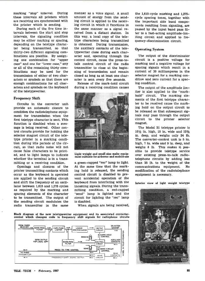
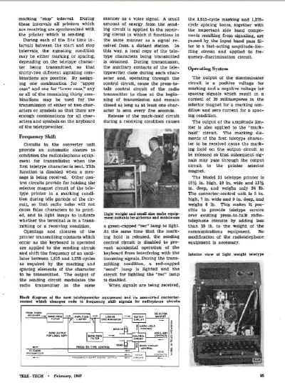
Light weight and small size make equipment
suitable for airborne and mobile use
a green-capped "rec" lamp to light.
At the same time that the marking
hold is released, the sending
control circuit is disabled to prevent
accidental operation of the
keyboard from interfering with the
incoming signals. During the transmitting
condition, a red-capped
"send" lamp is lighted and the
circuit for lighting the "rec" lamp
is disabled.
When signals are being received,
the 1,615-cycIe marking and 1,275-
cycle spacing tones, together with
the important side band components
resulting from signaling, are
passed by the input band pass filter
to a fast-acting amplitude-limiting
circuit and applied to frequency-
discrimination circuit.
Operating System
The output of the discriminator
circuit is a positive voltage for
marking and a negative voltage for
spacing signals which result in a
current of 20 milliamperes in the
selector magnet for a marking condition
and zero current for a spacing
condition.
The output of the amplitude limiter
is also applied to the "markhold"
circuit. The marking elements
of the first teletype character
to be received cause the marking
hold on the output circuit to
be released so that subsequent signals
may pass through the output
circuit to the printer selector
magnet.
The Model 31 teletype printer is
10y2 in. high, 10 in. wide and 13y2
in. deep, and weighs only 24 lb.
The converter-control unit is 5 in.
high, 7 in. wide and 9 in. deep, and
weighs 8 lb. This makes it possible
to provide teletype service
over existing press-to-talk radiotelephone
circuits by adding less
than 35 lb. to the weight of the
communications equipment. No
modification of the radiotelephone
equipment is necessary.
New lightweight teleprinter equipment extends
the usefulness of the system to include mobile
service in airplanes, trucks, for marine
service and in military operation where a printed
record of instructions, orders, etc., may be
received without continuous attention from an
operator and without the need for skilled operators.
|
|
Two Articles From Bell Laboratories
RECORD November 1946
HIGH FLYING TELETYPE (p 396-399)
:::::::::::::::::::::::::::
R. A. VANDERLIPPE
Telegraph
Development
:::::::::::::::::::::::::::
Another milestone in the history of radio communications has been reached, for
it is now practicable to send teletype messages to and from airplanes in flight. The
equipment which makes this possible is the new lightweight Model 31 teletype printer,
developed by the Teletype Corporation, and an associated converter-control unit,
developed by the Laboratories.
Smaller and lighter than a standard typewriter, this printer uses the regular teletype
keyboard and signaling code. The converter-control unit at a station which is
sending changes this code into frequencysignals in the audio-frequency range
for transmission over existing radio-telephone equipment. At a station which is receiving, the converter-control unit changes
these frequency shift signals into electrical impulses for operating the receiving-typing
part of the printer.
An interesting feature in connection with the use of this new instrument is that it will
work with any existing radio-telephone installation capable of carrying on satisfactory two-way voice communication. This,
of course, means that by the simple addition of the radio teletype equipment,
weighing less than thirty-five pounds, and without any modification of the radio-telephone equipment, two-way, typed communication, with all its advantages, may be
achieved. The normal use of the radio-telephone equipment is in no way affected by
the installation of the radio teletype.
A radio teletype network installed in aircraft and ground stations operates very
much like a press-to-talk radio-telephone network, except that instead of spoken
words it handles typed messages. No manual operation of a "press-to-talk" control is
required since the radio transmitter is turned on automatically when the first teletype character is sent. As in standard land
wire teletype equipment, two signaling conditions, commonly referred to as "marking" and "spacing," are used for transmission of teletype signals. The unit of time
during which a character is transmitted is broken into seven intervals. Each character
begins with a spacing "start" interval and ends with a marking "stop" interval. During
these intervals all printers which are receiving are synchronized with the printer which
is sending. During each of the five time intervals between the start and stop intervals,
the signaling condition may be either marking or spacing, depending on the teletype
character being transmitted, so that thirtytwo different signaling combinations are
possible. By assigning one combination for "upper case" and one for "lower case," any
or all of the remaining thirty combinations may be used for the transmission of either
of two characters or symbols so that there are enough combinations for all characters
and symbols on the keyboard of the teletypewriter.
Circuits in the converter unit provide an automatic closure to condition the radiotelephone equipment for transmission when
the first teletype character is sent. This function is disabled when a message is being received; Other control circuits provide
for holding the selector magnet circuit of the teletype printer in a marking condition
during idle periods of the circuit, so that radio noise will not cause false characters
to be printed, and to light lamps to indicate whether the terminal is in a transmitting or
a receiving condition.
Openings and closures of the printer transmitting contacts which occur as the keyboard is operated are applied to the
sending circuit and shift the frequency of an oscillator between 1,615 and 1,275 cycles as
required by the marking and spacing elements of the character to be transmitted.
The output of the sending circuit modulates the radio transmitter in the same manner as a voice signal. A small amount of
energy from the sending circuit is applied to the receiving circuit in which it functions
in the same manner as a signal received from a distant station. In this way, a local
copy of the teletype characters being transmitted is obtained. During transmission, the
auxiliary contacts of the teletypewriter close during each character and, operating
through the control circuit, cause the pressto-talk control circuit of the radio transmitter to close at the beginning of transmission
and remain closed as long as at least one character is sent every five seconds.
Release of the mark-hold circuit during a receiving condition causes a green-capped
REC lamp to light. At the same time that the marking hold is released, the sending control circuit is disabled to prevent accidental
operation of the keyboard from interfering with the incoming signals. During the
transmitting condition, a red-capped SEND lamp is lighted and the circuit for lighting
the BEC lamp is disabled.
When signals are being received, the 1,615-cycle marking and 1,275-cycle spacing tones, together with the important side
band components resulting from signaling, are passed by the input band pass filter to
a fast-acting amplitude-limiting circuit and applied to frequency-discrimination circuit.
The output of the discriminator circuit is a positive voltage for marking and a negative
voltage for spacing signals which result in a current of 20 milliamperes in the selector
magnet for a marking condition and zero current for a spacing condition. The output
of the amplitude limiter is also applied to the "mark-hold" circuit. The marking elements of the first teletype character to be
received cause the marking hold on the output circuit to be released so that subsequent signals may pass through the output
circuit to the printer selector magnet.
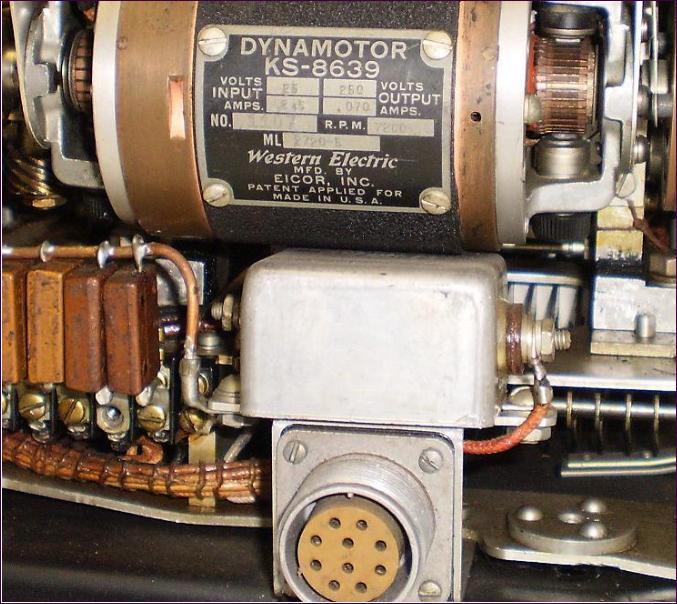
The primary source of power for the converter-control unit and the Model 31 teletype is the 26.5-volt battery commonly used
in airplanes. Plate voltage supply of +250 volts for the converter-control unit is normally obtained from a generator winding
on the teletype driving motor. This highvoltage supply is also used for an electronic
speed regulating circuit that is incorporated in the printer.
Tubes having 6.3-volt heaters are used in the converter-control so that this unit could
be adapted for vehicles having a 6-volt battery by reconnecting the filament circuits.
A vibrator type high-voltage supply circuit operating from 6-volt battery has been constructed for supplying plate voltage to the
converter-control unit.
The Model 31 teletype printer is only 10 1/2 inches high, 10 inches wide and
13 1/2 inches deep, and weighs only 24 pounds. The converter-control unit is 5 inches high,
7 inches wide and 9 inches deep, and weighs 8 pounds. This makes it possible to
provide teletype service over existing pressto-talk radio-telephone circuits by adding
less than 35 pounds to the weight of the communications equipment. No modification of the radio-telephone equipment is
necessary. An additional feature of importance to aircraft operation is the fact that
this equipment will operate in any position, even upside down.
With teletype operation, a printed record of all communications is available at all stations in the network. Messages may be handled easily and accurately by inexperienced
personnel, and are received without attention from the operator. Since a standard
teletype code is used, messages may be sent from any other teletype station such as a
land-wire "weather" network. In international service code groups of teletype characters could be standardized to cover all
routine phases of weather reporting, takeoff, landing and other instructions to be-given to the plane.
The new lightweight terminal equipment has special application to other fields in
which the large size and weight of standard equipment· has prevented the use of teletype methods of operation. These fields include mobile service to trucks, cars and
harbor craft and military applications to landing operations and forward command
posts of advanced echelons of a battle force. Of particular importance in these
uses is the advantage of making a record of instructions or other data without continuous attention from an operator. Also of
importance is the fact that messages may be handled easily and accurately by inexperienced operators.
|
|
THE AUTHOR: R. A. VANDERLIPPE attended the
University of Omaha and the University of Ne
braska from 1925 to 1930, receiving the degree
of B.Sc. in E.E. from the latter. While attending
Nebraska he also worked as toll-test boardman
and equipment engineer. He joined the Labora
tories in 1930, and worked on voice-frequency
carrier telegraph and d-e telegraph circuit design
problems. Later he supervised laboratory testing
of telegraph transmission circuits and laboratory
and field testing of private line telegraph switch
ing systems. During World War II he was con
cerned with the development of voice-frequency
carrier telegraph systems used by the Army and of
long-haul radio teletype apparatus and systems
used by the Army and Navy. At present Mr. Van
derlippe is a supervisor responsible for the de
velopment of radio teletype systems and of special
electronic circuits that are used in these and other
telegraph systems. (399)
|
|
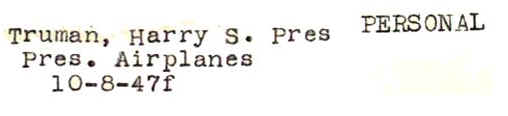
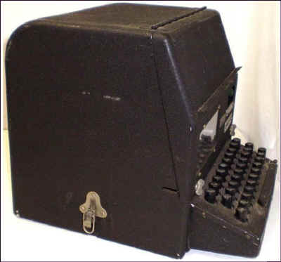
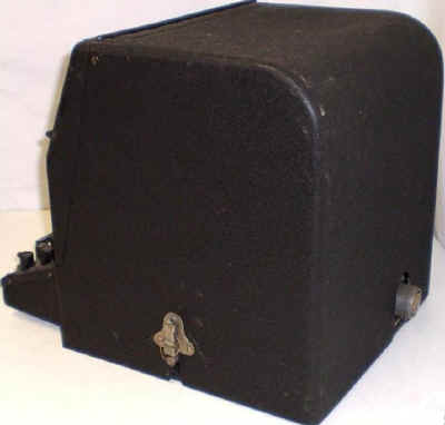
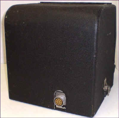
Teletypewriter and converter-control unit
for use with radio-telephone system |
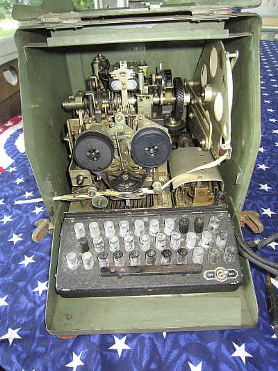
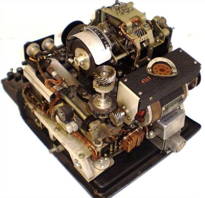
Interior view of the converter-control unit
|
|
Block schematic of a telegraph terminal
|

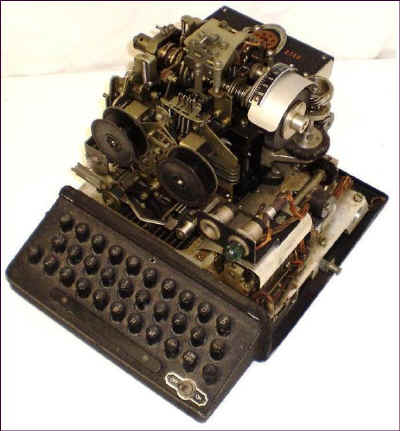
Interior view of the Model 31 teletypewriter.
It weighs less than 24 lbs.
|
"Picao"
at Indianapolis (p-420)
CAPTION-
Al Wilson in plane equipped for teletypewriter
and telephone service
Western Electric airborne teletypewriter equipment and the Bell System
radio-telephone system were demonstrated at Indianapolis during the
fortnight from October 9 to 23 for the benefit of 120 delegates from
some thirty-eight countries belonging to the Provisional International
Civil Aviation Organization. This international group is undertaking
to determine the most satisfactory instrumentalities for facilitating
world-wide aviation. Once decisions are reached, it is planned to have
standardized facilities adopted by all the participating countries
so as not to seriously handicap commercial planes
Hying transnational
routes by requiring them to be equipped with different navigational aids
for each country to which they fly.
Sponsored by the Civil Aeronautics Administration with the cooperation
of the State Department, the Army, the Navy, the Coast Guard, and the
American Aeronautical Radio Industry, the Indianapolis program was
held at the headquarters of the C.A.A.'s Technical Development Service
at the Municipal Airport. The Western Electric aircraft teletypewriter
system includes a lightweight teletype machine developed by the Teletype
Corporation and a small size lightweight converter-control unit
developed by the Laboratories. This system, described on page 396, was
demonstrated by Al Wilson and the mobile radio telephone system by
Walter Hunter, both of the Laboratories. In the capacity of official
observers at the demonstration were D. K. Martin of these Laboratories
and F. C.
MeMullen, Radio Division, Western Electric.
Guests of the exhibit had arrived a few days earlier from a similar
demonstration of British apparatus held in England from September 9 to
30. The delegates convened in Montreal on October 30 to determine
which of the air navigational systems they have seen in operation will
be specified for international adoption.
According to the program that was laid out, all the delegates spent
twenty-four hours in the air besides attending ground demonstrations and
lectures. During this period they had an opportunity to use the
teletypewriter and radio-telephone system as well as to study the
operation of the other navigational aids demonstrated.
|
|

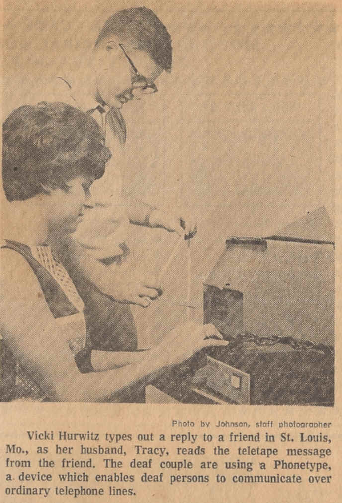
Teletype Model 31 used as a portable Telecommunications Terminal
for the Deaf and Hard of Hearing - Clipping from
the Paul and Sally Taylor Collection at SMECC
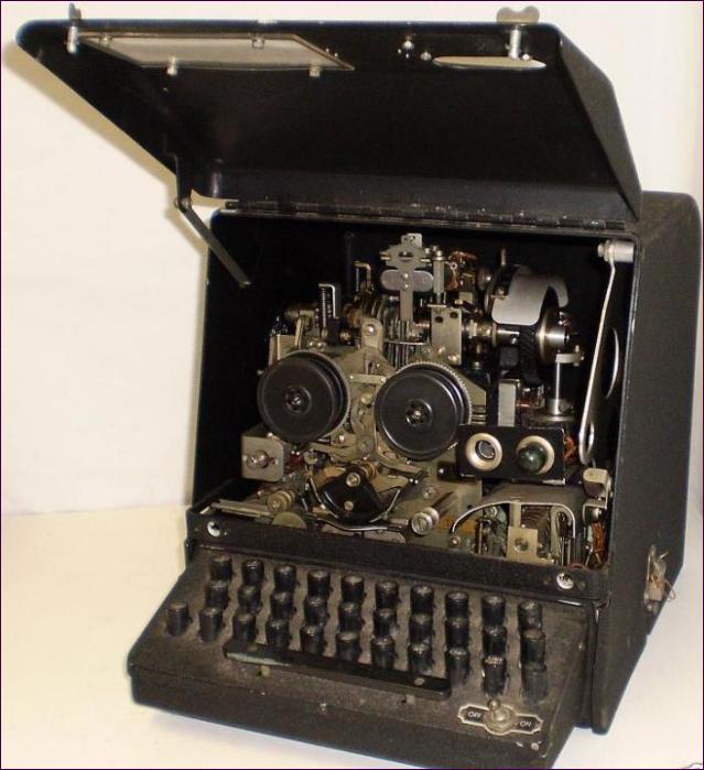
WESTERN UNION PORTABLE VERSION OF THE MODEL 31
TELETYPE
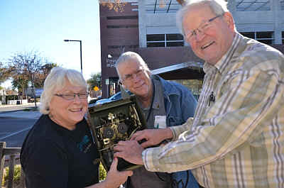
Teletype Model 31 from the Paul and Sally Taylor Collection
at SMECC prior to cleaning it.
Photo to the right shows Sally Taylor, Ed Sharpe Archivist
and Paul Taylor playing with the Model 31 portable.
We need parts to support this unit! Please let us
know of you have any model 31 spares, books drawings or stories!
|

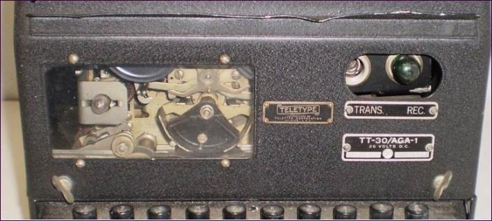
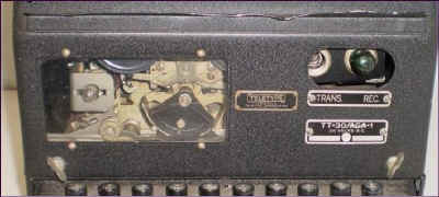
Military Version Teletype Model 31
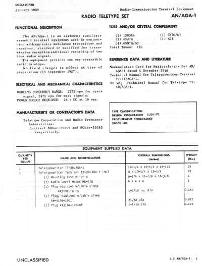
2275 cps Space, 2475 cps Mark Audio FSK adapter -
"used in conjunction with any voice-modulated
transmitter and receiver"
Includes
TT-30/AGA-1 Teletypewriter
(Teletype Model 31)
TT-31/AGA-1 Terminal Unit
TT-30/AGA-1
manual is here
AN/AGA-1 specification. do you have more info on this? Email info@smecc.org |
|
Photo Courtesy AWA
Enclosed is a scan of the Truman plane photo (AWA has an original
print). The date is "10-8-47" The operator is typing on a SIGNIN.
Which as far as I can tell is a M31 and a SIGCUM (or something similar) in
one package. Note that the TTY is an "ASR" with tape perf &
reader. (never seen any mention of that option on the M31 !).
The lower AN/ART-13 has a switch on the side labeled "Nornal <
> TTY" and a large vent probably for forced-air cooling.
Photo Courtesy AWA
A submitted group of Model 31 photos... sure
would like to buy this one ( or one like it!)

|
|
CLICK
TO SEE THE 14 PAGE PATENT! |
| Publication
number |
US2339313
A |
| Publication
type |
Grant |
| Publication
date |
Jan
18, 1944 |
| Filing
date |
Jun
9, 1941 |
| Priority
date |
Jun
9, 1941 |
| Also
published as |
DE917977C |
| Inventors |
Zenner
Walter J |
| Original
Assignee |
Teletype
Corp |
|
CQ Article Courtesy AWA Museum
Mod a tty 31 with toothed belts and pulleys??
Jim Haynes tells us: "On my recent Chicago trip I was given a
book of Teletype R&D practices,
mostly about how to negotiate the bureaucracy. One concerns filling
out a form to request more money for an R&D project, and they happened
to use a Model 31 case as an example of a properly done form.
It seems that somebody wanted a Model 31 with a synchronous motor.
They tried 1800 and 3600 RPM motors and found they had insufficient
starting torque. They were able to get sufficient torque with a
large capacitor, but it was too big to fit on the machine. They
felt the problem with starting was caused by the gears between the
motor and the mechanism, and wanted to try replacing the gears with
toothed belts and pulleys. And were asking for additional money to
carry out that part of the testing. I have no idea how it turned out;
I'm only aware of Model 31s with series motors that have inherently
high starting torque."
|