Doug Kerr explain about the
Teletype used
with typesetting machines at newspapers.
The Teletypesetter (TTS) system was developed by Teletype Corporation,
working in close collaboration with Merganthaler Linotype corporation.
The system used a six-bit code, essentially a superset of the Murray code.
The basic symbol repertoire comprised the letters a-z (lower-case), teh
digits 0-9, and a few important punctuation marks, plus various
non-printing formatting and control characters.
The character SHIFT shifted the mode so that the lower case letters were
replaced by their respective upper-case forms, and the digits were
replaced by further punctuation marks.
A common use was for the transmission of "composition-ready"
newspaper text.
In the basic scenario, an operator using a special keyboard perforator
would punch the text into six-track tape. This tape was read by a
transmitter-distributor (a Model 20, just like a Model 14 but for this
kind of tape and the associated line code)
At the receiving station, the signal went to a Model 20 reperforator
(signal-driven punch) and generated a duplicate of the original tape.
The composing machine (initially always a Merganthaler Linotype
linecasting machine) had been equipped with a Teletypesetter operating
unit. This sat atop the linecasting machine keyboard (with the
infamous ETAOIN SHRDLU keyboard arrangement, with the characters in order
of their frequency of occurrence in American journalistic English). At its
end, it had a reader for the 6-track TTS tape. It read the tape, decoded
the character, and pushed the corresponding linecasting machine key.
The operating unit had on its top a full set of keys, in the same
arrangement as the normal machine keys, which an operator could use to
manually operate teh machine. (They pushed the real keys, which of course
were hidden by the operating unit mechanism.)
In the 6-bit code, the code combinations for the letter characters
(considered to be specifcally lower-case unless SHIFT had been invoked)
were the same as for the corresponding character in the Murray case, with
the added bit (which for the moment I will call "x") as 0. The
portion of the code where "x" was 1 had the digits and numerous
punctuation marks and special typographic entities (which are beyond the
scope of this note).
There are many fascinating wrinkles to this whole system and its
implementation, but those too are beyond the scope of this note.
Now as to the tape. Starting with the basic 5-bit teletypewriter tape
(which was laid out, as seen with the tape advancing from us through a
reader, in the order 543.21, where the period represented the feedhole
track) the added bit track was placed at the far right, to attain a
symmetrical layout of three tracks on each side of the feedhole track.
Thus the layout, as seen with the tape advancing from us. and still using
"x" to represent the added bit/track, would be 543.21x.
Accordingly, it made eminent sense, from the standpoint of operators and
technicians, who of course could only "see" the code as manifest
on the perforated tape, to number the added bit track as "0",
for this layout:
543.210
Now in the transmission format it worked differently. The
"information bits" of a transmitted character were sent in the
order 123450. One explanation of a motive for this is that
monitoring printers intended to read the 5-bit code, with only a minor
timing modification, could "snag" bits 1-5 and print a
meaningful output (for the alphabetic characters, at least). I don't know
is this was ever actually exploited - I doubt it.
A further wrinkle in the TTS tape format is that the feedhole punches were
"advanced" with respect to the code punches. Approximately (I
don't have the actual spec at hand) the leading edge of a feedhole punch
aligned with the leading edge of a (larger) code punch.
The purpose was to avoid an operator accidentally inserting the tape with
the end first.
But what about what would seem to be the more serious problem, which edge
went where? Well, the operator could easily tell, since the "0"
track would have relatively few punches, as most of the characters would
in fact be letters.
By the way, the characters we speak of in regular typewriter operation as
"Carriage return" and "Line feed" were here called
"Return" and "Elevate". The latter (rather startling,
eh?) came from the linecasting machine itself. As the operator keyed
characters, brass "matrixes", little molds for individual
characters, were dropped from a large magazine and assembled to become
what would be a "mold" for casting a monolithic substitute for a
line of type ("line o' type", thus the trademark).
When a whole line had been assembled, the operator pushed a lever called
"elevate", This took the holder for the assembled line of
matrixes and raised it (aha!) to a "station" where is was
enclosed in a metal "case" and molten type metal (a lead alloy)
was injected to cast the "slug", which was ejected and stacked
in a rack to eventually form an entire column worth of "type".
So the "elevate" character caused the operating unit to pull the
elevate lever to cast the received line.
What about "Return"? Well, there were TTS page printers (the
Model 20 page printers - looked just like a Model 15) that could be used
to receive the TTS transmissions, either for monitoring purposes, or, for
"subscribers" to these news stories who did not have a line
casting machine (or did but it was not equipped with a TTS operating
unit), would produce paper copy that would be read by a hand compositor
(or the operator of the linecasting machine).
Now of course, such a printer works just like a Model 15 with regard to CR
and LF (that is to say, Return and Elevate). So teh originating tape ended
each line of copy with the sequence Return Elevate (or maybe, for safety's
sake in timing, Return Elevate Unshift, the codes that, in a 5-bit system,
would be CR LF LTRS).
The line casting machine operating unit would not do anything with Return
(so far as I know).
Best regards,
Doug Kerr
Here are some Teletypewriter pix.
I have embedded, rather than attached, them so I can provide annotation. I
assume you can "snag" them from that. If not, let me know and I
will send them as attachments.
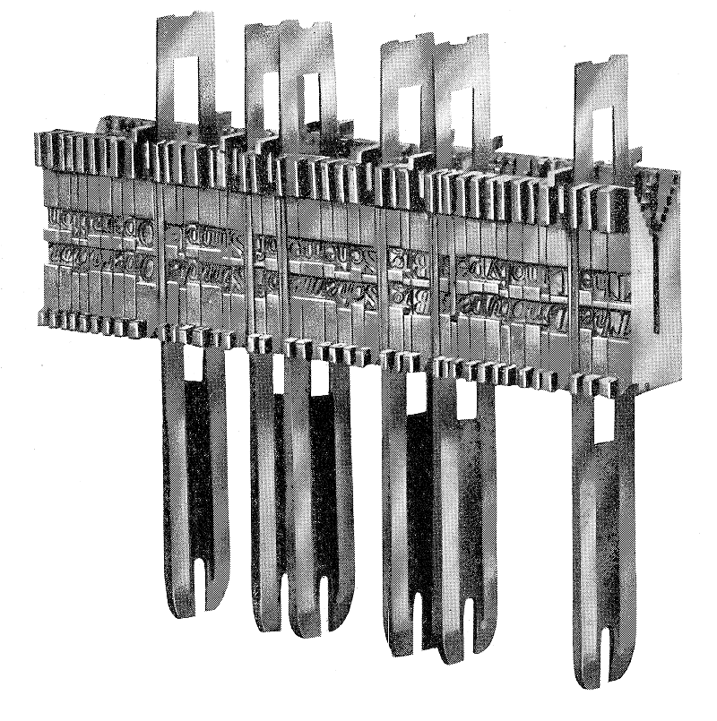
This is to show the principle of linecasting. The smaller objects are the
"matrixes" which are the molds for the individual characters of
a line. In this case, each in fact has the molds for two characters, one
normal and one italic. If the character is to be italic, the matrix is
shifted to put the italic "mold" at the battle zone.
The long objects are "space bands" They crate the spaces between
words. To allow justification, they are made of two mating wedges so their
overall thickness can change. After the vine is "assembled", the
set of matrixes and space bands goes into a "vise". whose jaws
are spaced by the finished width desired for the lines. Then the top
wedges of all the space bars pressed with a certain force so they will
expand, all to the same thickness, until the whole collection of objects
is "tight" in the vise, "justifying" the line. Then
the vise is moved into a chamber into which the molten type metal is
injected, casting the "slug" for the line.
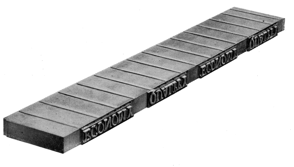
Here we see a slug with a part of a Linotype "slogan".
Here we see the slugs for two columns of a newspaper (probably), stacked
in a galley. We see a compositor replacing certain slugs that have been
recast to make corrections noted by the proofreaders from "galley
proofs" struck from the galleys of type. (The ink used for this has
been wiped off with a solvent - for many years gasoline was used - to make
this fellow's job less messy.
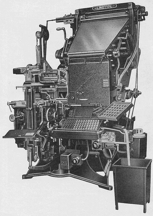
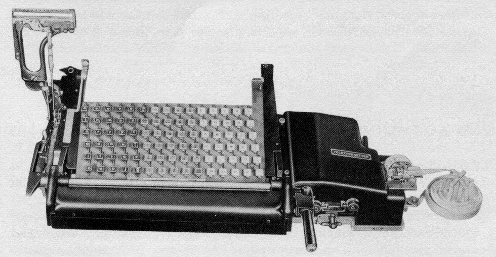
Here we see a typical older Linotype linecasting machine equipped for
Teletypesetter operation. The operating unit, which reads the tape, is on
the right.
The large trapezoidal object at the top is the magazine, which hods a
supply of each character's matrixes. They are dropped into the assembly
area by operating the keyboard.
When the casting of a line is done, the matrixes are freed and carried to
the top of the magazine and across it. There, by virtue of coding notches
on the matrix, each falls into its own compartment in the magazine.
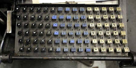
This shows a normal Linotype keyboard (this machine not equipped for
Teletypesetter operation). The left hand panel is for the upper-case
letters, the right-hand panel for the lower-case letters, and the center
panel for the punctuation marks and so forth.
The arrangement of the keys is in the order of the frequency of the
letters in American journalistic English - E, T, A, O, I, N, S, H, R,,D,
L, U, etc.
The lever at the left (somewhat worn) places a space band into the line
assembly - it is the machine's "space bar".
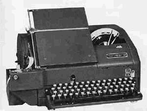
Here we see (on the right) the Teletypesetter operating unit, which reads
the tape, and the adapter keyboard, which decodes the coded character and
pushes the key levers of the existing keyboard. It has its own keyboard on
top for manual operation of the machine.
Ed: I had in my original article incorrectly said that the two of these
together were the "operating unit.".
Here we see a Teletypesetter perforator, which punches the tape by which
the "copy" is transmitted to the station where the linecasting
is done.
Ed: There is a great deal of complicated subtklety to the perforator. It
is not simply explained.I will prepare a supplemental article about that
as soon as I can.
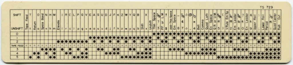
Here we see the Teletypesetter code, presented on a handy pocket
"ruler". This is a 6-bit "superset" of the 5-bit
teletypewriter code. The added bit is designated "0" to fit in
with its placement across the six-track perforated tape.
The basic character set provides for the lower-case letters, a-z, the
digits 0-9, and certain punctuation marks.
The character SHIFT changes the mode of the system so that the same
chaarcter ciodes represetn the upper-case letters, A-Z and other
punctuation marks and symbols, The character UNSHIFT returns the system to
its basic mode.
Well, its bed time for old telephone engineers (we have to get up early
tomorrow to get an early start as Carla has a civic-social event to attend
in the morning).
More later.
Isn't this all fun stuff!
Best regards,
Doug
------------------------------
I told you that the story of the Teletypesetter perforator was very
complicated, but here we go.
I will start with a picture of a typical one.

It might at first seem that it would be just like a Model 14 perforator
with four rows of keys, a sixth code bar, and a six track punch head. But
there is a complicated further wrinkle, to which we get a clue from what
looks like a 1956 Chevy speedometer at the top right.
First consider operation of a Linotype line casting machine in the usual
way. It of course did not have anything equivalent to the "automatic
word wrap" we enjoy today in our word processors. The operator had to
himself divide the "copy" into lines. Of course a character
counter would not have helped, owing to the differing widths of the
various characters.
Instead, the operator watched the assembler fill up with matrixes and
space bands (it was located so it could be "readily" seen). He
could see how much space was left before its "end wall." The
space bands were at this time all in their narrowest state. The operator
used his experience to tell him, for the number of space bands deposited
in the line, how much the line could "grow" in width if, later,
in the vise, the space bands were expended all the way. When the line
reached the point where the space bands could make it the full width, he
stopped adding characters and pulled the elevator handle.
Well, not quite. He of course had to be mindful of breaking between words,
or if that wouldn't work out, breaking a word and inserting a hyphen (of
course following teh complicated rules about where to break a word, which
might differ at this newspaper or book publisher from at others) You can
see that this was a very demanding job.
But now we are at a TTS perforation, where the operator has to emulate the
same thing, knowing how many characters to punch before she keys
"Return Elevate".
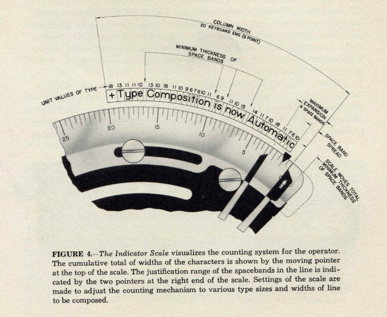
The is where teh "1956 Chevy speedometer" comes in. The
perforator is equipped with what we would today call a "lookup
table", wholly mechanical, which for each character key pressed
determined the width of that character in the Linotype machine font. For
each keystroke, a pointer on the "speedometer" advanced by that
amount.
The spacebar, however, did not do that. Remember, the width of a space
would vary over quite a range, depending on how fat the space bands were
made in the vise.
There were two more pointers on the speedometer, and as a new line was
started, they were at the position that corresponds to the assigned width
of the "column" for this publication. Each time the spacebar was
hit, punching a SPACE character, those two pointers moved
"down", one by an increment that corresponded to the minimum
width of a space band and the other by an increment that corresponded to
the maximum width of a space band.
Thus, the range of positions between them would, at any point in the
"composing" of the line, tell how much room there was for actual
characters.
So when the pointer that told how much space had been consumed so far by
actual characters moved to between those two pointers, the operator knew
she had a "full line", and would (usually) end the line at the
end of the current word.
When she keyed Return Elevate, all three pointers went to their starting
positions.
Now, of course the "mechanical lookup table" (it worked just
ilke a keyboard encoder, giving a binary output that was then translated
into an increment of movement of the main pointer) had to be designed to
give the widths of some particular font. But for different parts of the
newspaper, different fonts might be used. How is that accommodated?
Well, Linotype Corporation had designed a series of fonts all of which, in
any point size, had the same widths for all the characters (relative to
the point size).
Thus, one hookup table would serve all if there was provision for
"scaling" its output based on the point size, an adjustment that
was easily made on the TTS perforator.
Newspapers dependent on TTS operation would generally choose all the fonts
for body text, captions, and the like from this TTS-friendly font family.
(Headlines were generally composed on one of two other types of machines,
not usually set up for TTS operation.)
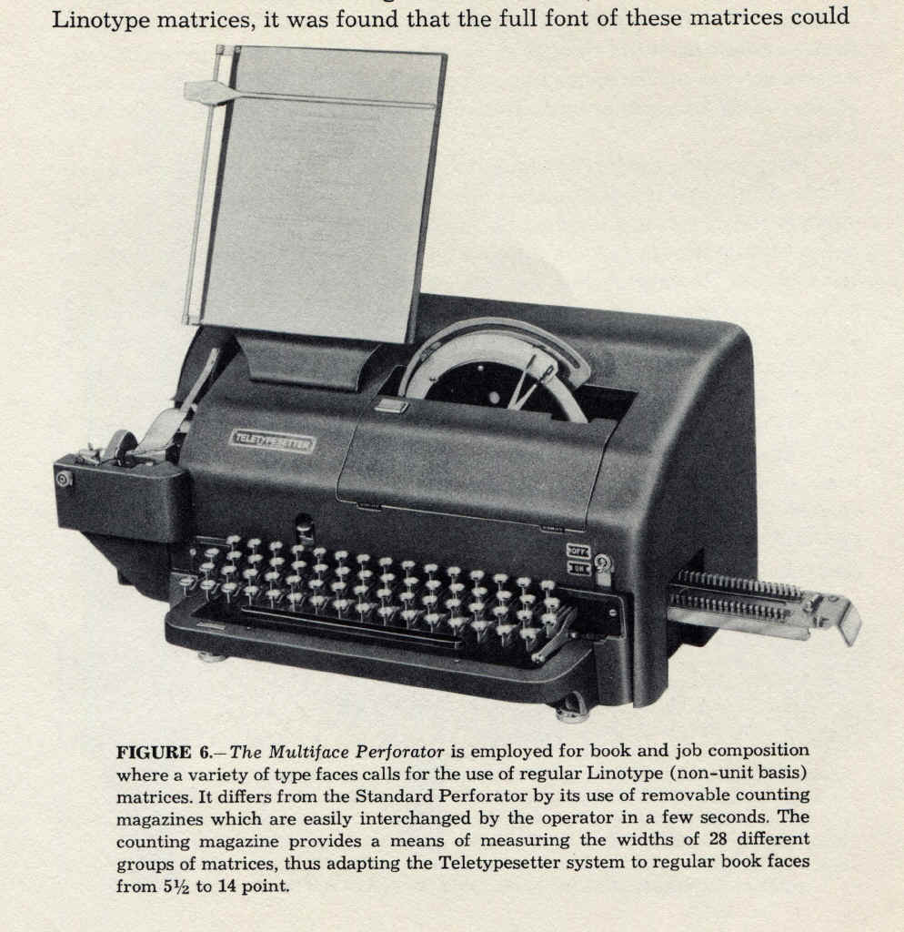
But in book publishing (another important TTS application), the book
designers generally did not want to be restricted to "TTS
friendly" fonts. To caaomodate this, another version of teh TTS
perforator had "plug-in lookup tables" (still wholly mechanical,
of course). These had about the proportions of a carton of American
cigarettes (but were of course smaller). They slid into the perforator
through a rectangular opening on the right side. Their input levers (one
per key) and output code bars (I forget now how many) engaged the
perforator innards when they were inserted.
So in a TTS perforating shop dealing with a certain book, there would be a
rack with these units (I forget just now what they were called) for each
font that would be encountered.
I will close with a trivial but wholly fascinating further detail. In a
typical TTS perforating shop, the "work stations": were located
quite close together. As a result, there might not be enough space between
adjacent perforators for the operator to slide a font module (they were
fairly long) into the right of the perforator. So the perforator had
to be swung around a bit to allow this operation. not too easy as they
were really rather heavy.
So there was a special accessory to facilitate this. A polished
stainless-steel plate was fastened to the bottom of the perforator, and a
thick felt pad was placed on the operating table for the machine to sit
on. This made it easier to swing the machine around to allow a new font
module to be inserted.
Amazing, wot?
Best regards,
Doug
This all came back to me after a few hints from the Internet!
The Linotype fonts that had systematic widths were called "unit
fonts". The name comes from teh fact that the character widths were
not only only consistent over various faces and point size, but were all
integral in term of the "units" used in teh output of the
"table lookup" in the perforators, so there would be no
accumulation of quantizing error.
The "plug in" "lookup tables" were called
"counting magazines."
He is a pic of the "1956 Chevy speedometer". I have not stripped
the commentary from it, as I thought it would be interesting.
Ah, here we see the perforator with interchangeable counting magazines
(called a "multiface perforator"), with a counting ,magazine
partially inserted. It was of course a bit longer than the keyboard was
wide.
and here we see a counting magazine itself:
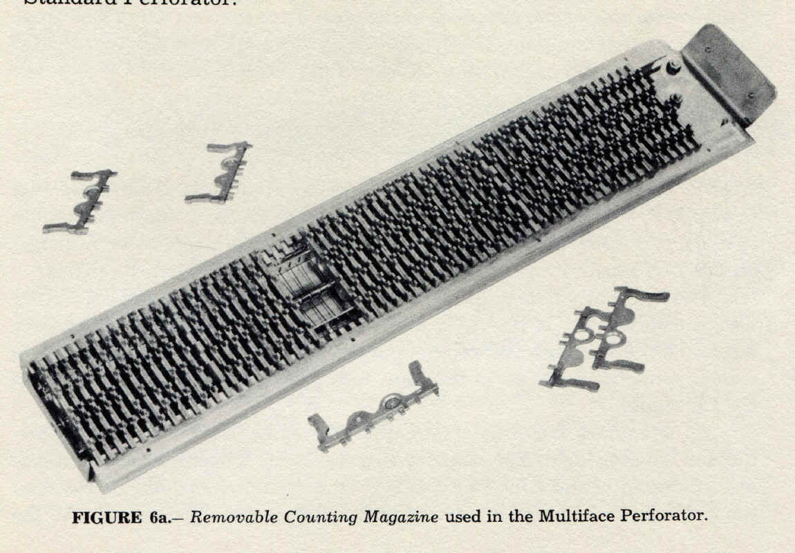
It is not as thick as I had remembered it.
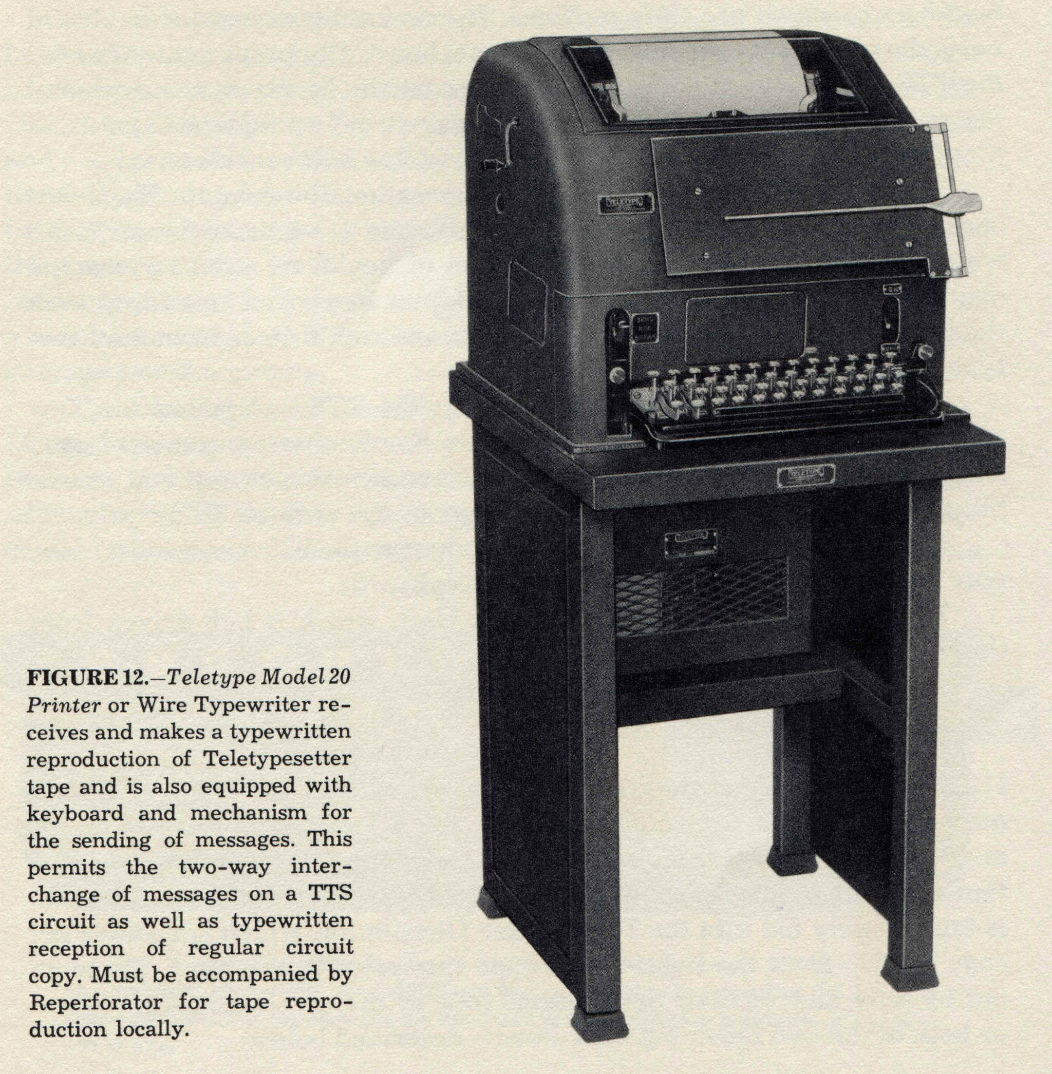
This is a 20KSR:
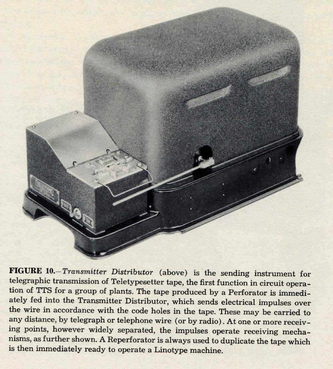
and a Model 20 Transmitter-distributor:
Best regards,
Doug
This figure::
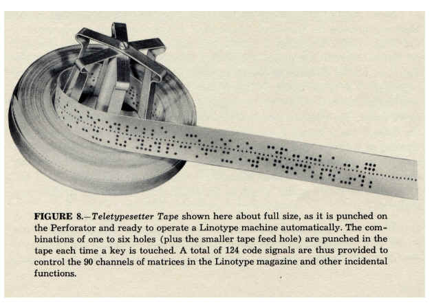
from a Merganthaler Linotype publication, certainly suggests the centered
arrangement of tracks on the tape. Of course there are few punches in the
0 track (we see a couple near the unwinder.
If you look carefully, you can see the "advanced" position of
the feedholes with respect to the code holes. Tape travel here is to the
right, as the tape comes off the unwinder. It is put on the unwinder just
as it was wound coming out of a perforator or reperforator, with the
beginning at the center. The tape is pulled from the center of the roll,
beginning first (duh!).
Best regards,
Doug
|
