Graymark Transmiter
Home ] Up ]


Graymark 515 home broadcaster

Graymark515.jpg (117045 bytes)              Graymark515layout.jpg (70863 bytes)

Click on small picture to make larger


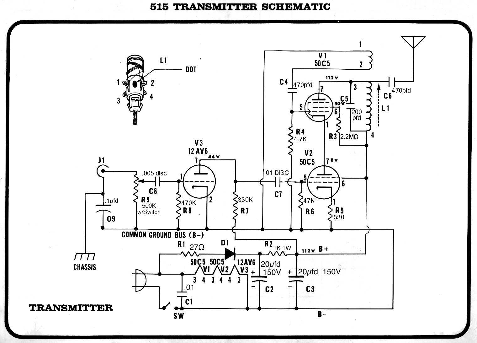
Attached is a Graymark 515 circuit. Variation of the WB with a neat stacked approach.  More power? Could modify the screen grid resistor/ voltage a bit I suppose.  Or increase B+ somewhat with a safer and better power supply.

The circuit for the 515 needs to be modified just slightly.  The 27 ohm resistor should feed both the diode and the tubes so that the filament voltages are not exceeded.

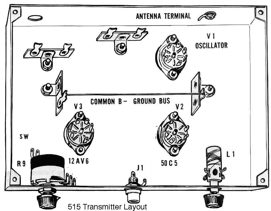
Have never seen the Graymark up close and personal, just have schematic and layout.

73,
Rich

Thanks to  C.R."Ron" Lawrence, KC4YOY for the photos!


Since High Voltages are used, these transmitters should only be built by experienced people, or under the supervision of experienced people.  

In Reality... DO NOT ATTEMPT TO USE THIS WITHOUT AN ISOLATION TRANSFORMER AS FATAL ELECTRIC SHOCK CAN TAKE PLACE.
- ed sharpe

Thanks to  Rich - KB8TAD for  assistance with scans and info.


Everyday we rescue items you see on these pages!
What do you have hiding in a closet or garage?
What could you add to the museum displays or the library?

PLEASE CONTACT US!

===================

DONATE! Click the Button Below!


Thank you very much!

===================

Material © SMECC 2007 or by other owners 

Contact Information for
Southwest Museum of Engineering,
Communications and Computation 
&
www.smecc.org

Talk to us!
Let us know what needs preserving!


Telephone 
623-435-1522 

Postal address 
smecc.org - Admin. 
Coury House / SMECC 
5802 W. Palmaire Ave 
Glendale, AZ 85301 

Electronic mail 
General Information: info@smecc.org