|
Welcome to the world of home wireless
broadcasting!
Below you can view a group of stories and memories of some of those experiences. We welcome the submission of your story to add to the collection here. We will also establish sections of review articles of home broadcasting units, schematics, etc. If you have anything that is not listed here please contact us and we would be happy to post it or if a three dimensional object add it to the museum's display. |
|||||||
|
|
|||||||
|
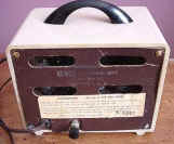
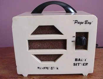
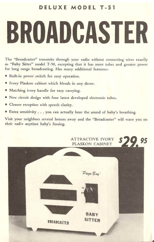
SEMCO ELECTRONICS DELUXE MODEL T-51 BABY SITTER BROADCASTER
Page Boy is a miniature broadcasting station adjusted to transmit at a frequency of 550 kilocycles to any radio and/or its own special receiver. Page Boy uses the ordinary electrical wiring in the building for "carrier current transmission". INSTALLATION:- Plug Page Boy into any 105-125 volt AC or DC outlet. (On DC, proper polarity must be obtained for both radio and Page Boy by reversing the plugs one at a time.) On Model T-51, turn switch to "ON' and allow 30 seconds for tubes to heat. Page Boy is now ready to broadcast any sound in the room. RADIO FOR_ LISTENING:- Tune any radio to 550 kc for listening, using the radio control to regulate the volume of the Page Boy signal. Should 550 kc be occupied by a radio station in your locality, an interfering whistle will be heard or the signal may be lost completely. In this event, a new transmitting frequency must be selected. RADIO BROADCAST INTERFERENCE:- To select a new frequency, plug radio into an outlet about 20 feet away from Page Boy and dial to a silent spot near 550 kc with radio volume on about half way. Then adjust screw in back of Page Boy by rotating slightly (VERY SLOWLY) to the left (500 to 550) or right (550 to 600) until a howl (acoustic feedback) is heard at the loudest level. Reduce volume on radio and retune to finest point. You now have determined the new listening frequency for use on this radio as well as on others. The Page Boy signal can also be heard with reduced power in the harmonic range which is double and triple the original frequency. For instance, if the pre-set frequency is 550kc, the signal can be heard at 1100 kc and 1650 kc. WEAK SIGNAL or LACK OF COMMUNICATION:- Be sure your radio is tuned in accurately. It is best to retune your radio after Page Boy has been on for ten minutes. While the use of Page Boy is simple and non-critical and transmission may be effected over long distances (on the same power transformer), its full efficiency may be impeded in circuits which are heavily loaded with large motors, oil burners, elevator mechanisms, electric heaters, hot plates, flat irons, toasters, etc. Separate circuits or an intervening transformer in the electrical circuit will block the Page Boy signal and can be overcome by installing a simple and inexpensive capacity bridge at your fuse box or across the terminals of the transformer. HUM or NOISE:- Hum is not normal during Page Boy operation. It is usually caused by your own radio which is generating the noise or hum. Many small AC-DC radios in use have no proper isolation of their rectifying action from the power line, causing a hum or buzz. This will not prevent transmission. If the noise is not objectionable, it can be disregarded. Should you find it objectionable, our specially designed Z2 filter will correct the situation. Simply plug the filter into the electric socket; then plug your radio into the filter receptacle. Noises from electrical appliances which interfere with ordinary radio reception will also interfere with the Page Boy signals. Our Z2 filter may also be used on the offending appliances and the results in quieter radio reception as well as Page Boy operation are usually worth the investment. IMPORTANT---DO NOT CONNECT FILTER TO PAGE BOY UNIT. |
No wiring needed! No installation! Simply plug in like a lamp The "Broadcaster" transmits through your radio without connecting wires exactly as "Baby Sitter" model T-50, excepting that it has more tubes and greater power for long range broadcasting. Has many additional features: · Built-in power switch for easy operation. · Ivory Plaskon cabinet which blends in any decor. · Matching ivory handle for easy carrying. · New circuit design with four latest developed electronic tubes. · Clearer reception with speech clarity. · Extra sensitivity. . . you can actually hear the sound of baby's breathing. Visit your neighbors several houses away and the "Broadcaster" will warn you on their radio anytime baby's fussing. ATTRACTIVE IVORY PLASKON CABINET
This text from brochures provided
by Jonathan D. Bromberg - W1JDB We have other brochures and
units of other
|
||||||
|
SEMCO Electronics 'Page Boy Electronic Babysitter Tube type from the 50's In the Museum's collection. Many units were produced to monitor children remotely. Of course many industrious young folk got hold of them and turned them into neighborhood broadcasting stations also! |
|||||||
|
This link will take you to schematic and chassis layout diagram. |
|||||||
|
|
|||||||
| Folks were asked about early experiences with wireless broadcasting from the home as a youth and here they are... | |||||||
|
|
|||||||
| Gerald Newton Tells Us:
As a matter of fact at the age of 13 my Dad bought an
old 78 rpm phonograph. |
|||||||
| David Creel Tells Us:
I grew up in Birmingham, Alabama, and my father was a
United Methodist pastor there in the late 60's. As a hobby, my dad
restores and collects antique radios, so I owe much of my early
electronics experience to him. At the time, Dad also had a couple of
radio programs on the local Christian radio station, WDJC. After a few
visits to the station, and after meeting their Chief Engineer, I was
hooked on radio. Around age 11, I built a small studio with two
turntables, a cassette deck, a small battery powered mixer, and a cheap
crystal microphone. Later, I got a nicer dynamic mic with a boom -- boy
did I feel like a pro then! Since the mixer didn't have a cue function,
I modified a small "speaker selector box" that my dad had for
the purpose of off-air cueing. I don't remember the manufacturer of that
little box, but obtained a "Gates" nameplate from the WDJC
engineer so it would look more professional! I also had one of those
"suction cup" telephone pickups so that I could take
"on-the-air" requests from my friends. I even built a
"tape delay" for the telephone using an old reel-to-reel
recorder which I had modified by adding a loop of tape and an extra
head. My first transmitter was a CB walkie talkie, operating on Channel
14. I found that a harmonic appeared at 108 MHz, so I called my station
WNSM (Weather, News, Sports, and Music) at 108 MHz FM. Yeah, I know it
probably wasn't legal, but it was all I had! Later, I got a small
electronics kit and built a very low power transistorized
battery-powered AM transmitter -- never got much range out of it though.
Shortly thereafter, a friend at the local electronics store gave me a
Knight-kit Wireless Broadcaster and Amplifier. Using the new transmitter
and a variety of antennas, I was able to broadcast over a range of a few
city blocks. My friend, Lee, helped me with the "DJ" work. We
eventually built a small station at his house, too. At age 13, I got my
first Amateur Radio license (WN4YKJ), but still couldn't get
broadcasting out of my blood.
When my family moved to Sheffield, Alabama in 1972, I again set up my little radio station. This time, I found a friend named Jimmy who had similar interests, and before long we had a two station network! This time, another friend named Jim, helped with the "DJ" work. I would often play a full album side and ride around the neighborhood on my bicycle to check the range of the station. Somewhere around that time, I built a new transmitter using a 12AX7 pre-amp, and two 6C4's for the oscillator and modulator. Using a variety of antennas, I was able to extend the range to where the station could be heard, albeit with some difficulty, about 2 miles away in nearby Muscle Shoals where many of my friends lived. I settled on the frequency of 770 kHz and began using the call letters "WABC." I wanted to sound just like the real WABC from New York which I often listened to at night. I even taped their jingles so that I could sound more professional. I never quite got broadcast engineering out of my system. I attended Auburn University and got a degree in Electrical Engineering in August of 1983. During those years, I had the opportunity to visit HCJB in Quito, Ecuador and developed a keen interest in shortwave radio. In my Senior year, I worked at our campus radio station, WEGL, doing some on-air shifts and engineering work. After graduation, I worked for Alabama Power Company for 7 years, but again, couldn't get radio out of my system! I got back into ham radio around 1986, this time receiving the call sign KB4TXM. In 1990, I left Alabama Power to serve as a missionary radio engineer with the Far East Broadcasting Company on the island of Saipan where I am now the Chief Engineer for International Shortwave station KFBS. So, you see, I am another broadcast engineer who got started using the Knight Wireless Broadcaster. David Creel (Amateur radio call sign AH0AM)
|
|||||||
|
KD4HSH Tells US:
I have one of the little Knight-Kit blue TX
myself. I built it around 1960.. The thing remembered most is that I got a
few nasty shocks when hooking it up to my sisters little portable phono
which was also hot chassis. |
|||||||
| Brian Carling Tells Us:
No pictures I am afraid, but mine was a homebrew 807, Bob Richards Tells Us:
Growing up I was always fascinated by radio,
and the music I heard on it. in 1955 at 21 I got a part time job
at KEEN in San Jose. I later relocated to Downey and got a job
with General Telephone.
It was 1956 and Rock and Roll was happening,
but not many stations were playing it yet. I decided to broadcast
my 45 collection so the neighborhood guys could hear it. (Mostly
teenage friends of my brothers). So I bought a one tube phono
oscillator which had a one foot wire on it for an antenna. I added
a power supply and a 6L6 as a broadband amp. It was AM.
Then everyday at a set time I would play tunes and take phone requests
from the neighborhood.
I attached a long wire to the output (maybe
100 feet) and attached one end to a telephone pole in the back yard.
The result was that in front of the house the signal only went about a
block, but the opposite direction it went over 5 miles. Somehow, I
had made a directional antenna that was horizontal to the ground.
It was great fun.
BTW, I remember that summer watching Elvis
live on the Tommy Dorsey Show which was the summer replacement for
Jackie Gleason.
I later got back into radio at KWOW in
Pomona (1960) KCKC San Bernardino 1961, KACY Port Hueneme, 1962
-1968
KABC, KNX as an engineer, then KBBQ from
1969 to 1973. KBIS in Bakersfield in 1975 and KARM in Fresno in
1976-79.
Then I went to work for Cetec Broadcast
Group. In 1980 I programmed KMEN in San Bernardino with one of the
first Cetec computerized automation systems. It worked great and
eliminated a bunch of jobs, including mine. After that, I went
into Sales and Marketing, working for CRL in Tempe Az. until 1989.
Then KMIX in Ojai, Palmdale, Escondido, Las
Vegas (KOW 870), then Riverside at KOLA for a year, and then back to
Thousand Oaks where I rebuilt KNJO after a fire and became Ops Manager
and worked on air with Sweet Dick Whittington. When that sold, I
returned to contract engineering.
I recently contacted a local station about a
job and was told they paid $7.25 an hour. Guess I'll stay home.
Bob Richards
|
|||||||
Tom Hoehler tells us:
Hi, saw your posting on the sci.electronics. repair group. Yes, I had a neighbor who had built a Knight Kit broadcaster/preamp (you could also use this thing for a mag. phono preamp too!) Of course, we had to put a very long antenna on that bad boy and got it to broadcast about a half mile if you used a car radio to pick it up. Then he moved away and my broadcasting days were over for a few months till one day I was talking to another older neighbor and recalled on how much fun we had with that little broadcaster. He brought me an old Philco phono oscillator/78 rpm turntable combo. This thing was meant to be placed on top of a radio back in the thirties. Then you could play your 78's thru the radio. It had two tubes, a rectifier and a pentagrid converter. After we modified the input to accept the output of a preamp, we were ready to go. We had to mark the plug so we would plug it into the wall correctly or the hot chassis would knock you on your butt! Again, with a long wire antenna, this thing would put a pretty good signal in a four square block area. Alas, the pentagrid converter filament opened one day, and since this was the sixties, the tube was almost impossible to find. By then, I had acquired a bit of electronic knowledge, so I built a serious AM transmitter. I had a 1610 khz crystal made by Texas Crystals in FL, and used a 6V6 as an osc, driving a 6146 plate modulated amplifier. I used a speaker output transformer hooked up backwards as a modulation trans, drove it with a Knight Kit 35 watt hi fi amp. Since I was using an old television power transformer and a 5U4 rectifier, input was limited to about 30 watts. I built a matching network and loaded it into my Mom's steel clothesline. That thing could be picked up a good five or six miles away, it is a wonder the FCC didn't come knocking! We would make a dj tape, start it rolling and go out and listen to it in the car. We called it WLST, what a blast from the past! When asked about the disposition of the Philco and the homebrew transmitter, Tom tell us: Unfortunately, I don't have either unit. I'm sure the old Philco was trashed, and my serious AM transmitter was sold to a kid in Dallas. I worked for Texas Instruments, and one of the dispatchers was a student at a local college. They wanted a low power transmitter for a campus radio station. So, foolishly, I sold it for 75 bucks. I think I still have a photo of it somewhere, I will dig it out and scan it to you. Most of the circuitry was lifted from an old 1957 edition of the ARRL handbook my grandfather gave me. Of course, the L and C of the tuned circuits had to be increased to tune to the broadcast band, but with the help of a borrowed grid dip oscillator and a big hunk of 2 inch diameter Air Dux, we were on our way. I had metering circuits for the grid and plate of the final, it was easy to tune up. We used a very simple tech school oscilloscope as a modulation scope, worked like a charm. We had to make sure the grounding was quite solid, for if not, you would get nasty rf burns from the preamp, or the turntable tonearms or the mic. You haven't lived until you get an rf burn on your lips while trying to read the weather forecast from the local paper! It really was a lot of fun, but I did not pursue broadcasting as a career. Instead, I worked for the Louisville Police Dept as a radio tech for seven years, then switched to medical equipment sales and service, and that's what my five partners and I do today. I don't get to use my electronics skills as much as I once did, the manufacturers handle most of the board repairs today due to liability issues. That's my story, hope you enjoyed reading it! |
|||||||
|
Black Thread and
Ford Coils Pete Petersen
WY7Z In my old neighborhood over 60 years ago, Gene and Kenny were my close friends and school chums. Gene lived on a corner and I lived two houses away. One day we decided to put up a string an and tin can telephone between our houses. Empty cans and spools of black thread were quickly provided by mothers happy to supply whatever might keep us out of mischief. The lady in the intervening house gave us permission to put our telephone line across her yard and through her tree after we promised not to fall from the tree and break our necks. It took many tries and much broken thread before the telephone was a success. volume was adequate, as I recall, in spite of the thread rubbing against tree limbs. We tried without success to string a second line between Gene and Kenny’s house. Their houses were separated by a broad street with a grassy median wide enough for us to play football in. We succeeded in running thread between their houses but the distance was too great and the thread sagged so much in the middle that a passing truck carried it away. Some other communication system was needed. I don’t recall whose idea it was, but a wireless system was proposed using Model T Ford spark coils. Ford coils were marvelous things, housed in a nicely joined wood case with a vibrating current interrupter on one end. They produced a high enough secondary voltage to make a blue spark jump across a half inch gap. By asking around the neighborhood we found several men who had owned Model Ts and who gave us left over coils. 6 volt batteries were free also; service stations were glad to give away old batteries that would no longer start a car but had enough power for our purpose. The transmitters were simplicity itself: a Ford coil, a homemade spark gap, wires for the aerial and ground, and a telegraph key made from a hacksaw blade.. Of course we knew nothing about amateur radio, licensing, frequencies, Morse code, or other niceties. Being completely untuned, these transmitters probably covered the entire radio frequency spectrum. That was good in a way because we could receive our signals with any broadcast receiver tuned to any frequency. Fortunately there was no television to interfere with and we never heard any complaints about interfering with radio broadcasts. The latter was probably because we lived in a working class neighborhood where radios sere usually operated by the man of the house after dinner when we were doing our homework or were in bed. With our family receiver dials set anywhere to hear the buzz of our transmitters we communicated with something similar to Morse code. Kenny was one buzz, Gene was two buzzes, and I was three buzzes. Various combinations of short and long buzzes meant let’s play ball, go to the movies, or whatever. This system lasted less than a year. Gene and his family moved away first and Kenny’s family left a few months later. I never saw or heard from them again. I still have my ford coil and spark gap though, and if I ever hear a familiar buzz on the radio I can be set up to answer in minutes.
|
|||||||
|
Kit a Knight
in Shining Armor 
by Jack Cheese
(reprinted from Radio World, April 1, 1987)
Back in 1964, when it was still profitable to
operate a local AM daytimer, KHGL signed on the air in Pasadena, CA.
The station operated on 860 kHz and covered the city of license
well using an end-fed long wire antenna.
But even in the heyday of AM radio, dollars were
tight, and the station's construction budget had to be watched
carefully.
For this and various technical reasons, the
transmitter we chose for the new KHGL was a model manufactured by
Knight Electronics. The Knight transmitter (or Knight-Kit, to be
accurate) was ideal for our application.
The transmitter was compact, taking up only l/2
square foot of floor space, and could be powered by 115 volts AC or
DC, single phase. There was no need to install three-phase AC service.
It used only three tubes and didn't have any
unusual cooling requirements. In addition, the Knight
transmitter included a built-in turntable and microphone preamplifier,
modulation level control and an audio output for monitoring program
modulation with a conventional loudspeaker.
Even with a relatively low output power of 100 mW,
the Knight AM transmitter was rather cost-effective with a price tag
of under $12 (plus shipping via UPS).
There was only one catch: As it's name implied, it
was a transmitter kit; the buyer had to build it.
The Knight unit was assembled using point-to-point
wiring, 1964 was too early for PC board technology.
Do-it-yourself assembly
Assembling the Knight-Kit transmitter was
straightforward, thanks to a well written and illustrated manual. The
process took about two days.
The transmitter design was conventional, employing
three tubes: two type 50C5 beam power pentodes and one 12AX7A dual
low-noise triode. One of the 50C5 tubes was the oscillator/RF power
amplifier.
The carrier was generated using a free-running
oscillator, the frequency of which was determined by a variable
capacitor in the “tank” circuit. The operating frequency was
adjustable over a range of 530 to 1610 kHz.
The RF output was taken from the plate circuit of
this same tube, and coupled to the antenna with a broadband output
circuit. There was no need for plate tuning or loading adjustments;
the output section was broad enough to permit adequate efficiency on
the entire AM band.
The RF oscillator/PA tube was plate modulated by
the other 50C5, the modulator. The modulator circuit was also
conventional, except that the modulation transformer primary was wired
to the plate of the PA, and its secondary was therefore available for
connection to an 8 ohm speaker. This provided a convenient means
of monitoring the modulating signal and eliminated the need for a
separate mod monitor.
The most unique aspect of the Knight Kit
transmitter was the inclusion of an RlAA-equalized magnetic turntable
pre-amplifier.
Never since have I seen any transmitter that
actually had an RCA jack on it labeled "mag-phono input. The
12AX7A tube was the phono preamp, and would provide more than adequate
modulation level when used with the recommended GE VRII cartridge.
A ceramic microphone was also provided, and would
work when plugged into the "phono" input, though the RIAA EQ
created somewhat exaggerated bass response.
When the Knight transmitter was first powered up,
there was an unusually bright momentary flash from the filaments of
the 12AX7A tube. We determined this was because the 12AX7A did
not have an 11 second controlled warm-up as did the 50C5's, and this
was normal. (The tubes' filaments were powered directly
from the 115 volt AC line.)
When all tubes reached their operating condition,
full RF output was realized. The transmitter was operating perfectly,
though off frequency. The tuning capacitor was adjusted (with
full RF output) until the correct frequency was obtained, as noted on
a nearby RCA Victor AM receiver.
Before regular programming could begin it was
necessary to run a Proof of Performance. Frequency response was tested
using an audio generator, and confirmed expected response from 100 Hz
to 8 kHz, being down 10 dB at 50 Hz and 11.2 kHz. Distortion was
also checked ... it averaged about 5% throughout the pass band, rising
to 10% at 100 Hz.
The lack of low-frequency response and excessive
LF distortion was evidently caused by the limitations of the minute
modulation transformer.
Noise performance was a bit disappointing. The
SN ratio was only 30 dB at best, referenced to 100% modulation. Most
of the noise was low frequency hum; reversing the AC line cord in the
socket helped only a few decibels. Even shorting the audio input
had little effect. I suspected an AC ground loop in the chassis ground
connections.
Since the Knight transmitter would operate from AC
or DC, we actually connected 110 V worth of batteries to the unit and
powered it from pure DC. The hum remained. I could only assume
that there was RF pickup somewhere in the audio circuitry causing the
problem. Other than that, the audio performance was respectable.
Modulation was adjusted via a front panel knob
(violet knob with white dot) to a maximum of about 85%.
Connecting a speaker to the audio monitor output
lowered this to 70%, evidently due to the limited power output
capability of the 50C5 modulator tube
After the performance tests were complete, KGHL's
regular programming began in the summer of 1964. It was very hot, yet
the Knight-Kit transmitter performed flawlessly even with no cooling.
Frequency stability was good, with less than 50 kHz of drift after a
30 minute warm up period.
Only after three years of constant use did a
problem develop: the selenium rectifier stack failed, causing a loss
of plate HV, and producing an overwhelming odor in the control room.
Repairs were made in a few hours, and the
Knight-Kit transmitter has been on the air ever since. A few rust
spots have appeared on its once-gleaming blue chassis, but the
transmitter has been reliable for over 20 years.
Fly by Knight
Unfortunately, Knight Electronics has been out of
business for several years, probably due to stiff competition from
"the big boys."
There were several hundred Knight AM broadcast
transmitters made in the '60s, some of which are still on the air
today. They are an excellent choice for many AM daytimers,
especially those with low-power pre-sunrise operating authority.
Though a used Knight transmitter will command a
high price, usually well over five dollars, checking RW's used
equipment listing will be worth the effort if you find one of these
fine works of engineering expertise.
At KHGL, we wouldn't have anything else. As the
saying goes ... "'It' keep station profits high as a kite, you
must be on the air, Knight after Knight!"
Jack Cheese is CE of KCHZ Powercheese Pario (formerly KHGL) and surfaces once a year on April Fools Day. His alter ego, Hank Landsberg is president of Henry Engineering and can be reached at http://www.henryeng.com/ and does not take kindly to the label "fool." Reprinted with permission: Hank Landsberg Henry Engineering |
|||||||
|
A
Zephyr, with a sticker on the bottom gives instructions on using
this “miniature broadcaster,” with which you play your records over
your radio set. Can you tell us more about this?
|
|||||||
|
A
LINE-OPERATED ONE-TUBE RADIO (TRANSMITTER)
Actually, I was looking over some different schematics for one-tube
radios in back issues of the Horn Speaker, because I was intrigued by the
idea that a radio could have just one tube.
All the other sets I'd seen at the club meetings and auctions had
lots of tubes, and I learned these were to multiply the gain of the signal
from the antenna, which is weak everywhere but in parts of Wheaton, Md.
where I live.
The set I chose to build used the circuit of figure 1, and it had
an O1A tube. Not wanting to
get a five-volt battery to light it, I thought of using a cheaper tube and
a 6-volt transformer from Radio Shack, plus I wanted plenty of gain, so I
reworked the schematic to make the set play through a speaker!
That changed the design to the circuit of figure 2.
Little did I realize what a change that would actually make!
I had all the parts
but a breadboard - the guy at Radio Shack told me I could use another
6-volt transformer for the output transformer and proved it with an
equation, and I also bought an isolation transformer the guy thought I
might need. He advised me not
to use plastic solder and gave me some other tips.
My antenna was a 50-foot length of wire strung around the corners
of my workshop. I removed all
the insulation from the wire, too, so as to increase the gain.
When the circuit was finished, I turned on the power and was
rewarded by the sight of a cheerfully glowing 6C4.
I also had a cheerfully glowing rectifier diode, until I reversed
the polarity of the filter capacitor.
Finally, the set seemed to be working right, and I tuned the
variable condenser (I think it's really a capacitor, too) looking for
stations.
All I had in the speaker was a low hum, so, deciding I needed more
gain, I went back to Radio Shack and bought a 15 inch speaker.
When I hooked this baby up, things started to happen!
It was this way: I had another radio on in the shop at the time,
listening to Lush Rimbaud over WMAL, which is the only other station I gan
get here in Wheaton so close to that 50,000 watt tower.
Suddenly there was a rhythmic sound coming from the radio that was
like a crazed rhino crashing through the brush.
Lush never gets carried away like that, so I looked around for the
source of this new interference. Imagine my surprise when I saw my dog
Nipper sniffing excitedly at the new Radio Shack speaker - every time he
touched the cone, there was another panting crashing sound from the shop
radio. Apparently my one-tube
radio was actually working backwards, taking the noise of Nipper's
sniffing and transmitting it over my new antenna to the shop radio.
I tested this theory by changing the tuning condenser of my set,
and sure enough, the dog moved up in frequency to about 800 on the dial!
I learned many things by designing my own radio using the circuit
of figure 2. I found out
that:
1.
A speaker can act like a microphone.
2.
Radios have the property of reciprocity.
3.
An isolation transformer can prevent a nasty
shock.
4.
Capacitors can also be condensers, and some of
them can be hooked up backwards.
5.
If you have enough gain, you don't really need a
ground these days.
6.
When I connected my tape player to the speaker,
the music came over every radio in my house!
This last finding really hit me.
I had designed a transmitter.
That has to be harder than designing a receiver.
Now I use the circuit of figure 2 (and the isolation transformer)
to broadcast music all over my house and I can also hear it in my Walkman
outside!
Finally, I'm not completely sure about the finding of item 2 above.
I tried shouting into the speaker of every other radio in my house
to see how well each one would broadcast, but got no result except with my
own design. Maybe it's
because my workshop antenna has so much more gain. Dick Parks April 1, 1993 |
|||||||
|
|
|||||||
|
Charles Ring writes in - "Here are scans
of the two sides of the sheet I have about one of my dad's phono oscillators. Found it today while looking for my old ham logbooks. I've never seen a maker name for this one, just the model name TM-6X which does not appear on the unit itself." OK Folks.... Who made the TM-6X and when was it made!? EMAIL us!
|
|||||||
