|
POPULAR ELECTRONICS
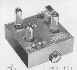
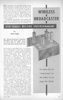
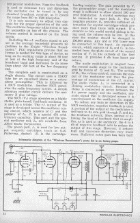
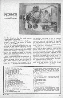
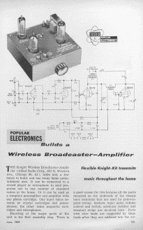
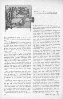
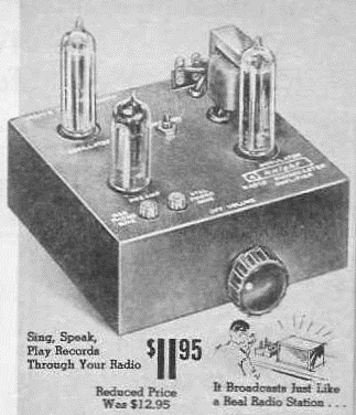
The Knight Wireless Broadcaster-Amplifier, (Allied Radio Corp. 100 N Western Ave, Chicago 80, Ill.), takes only a few hours to build, and has many home entertainment uses It can be connected to a record player, or microphone to send programs out to any number of standard radios in the house. 0r it can be used a, a complete preamplifier, and amplifier, with any phono cartridge One input takes ceramic or crystal cartridges and microphones; the other takes magnetic cartridges and microphones. Mounting of the major, parts or the unit is the first assembly step. There is a good reason for this because all the parts mounted on the underside or the chassis have terminals that are used for point-to-point wiring. Sockets. input jacks, volume control and switch. selenium rectifier and terminal strips are involved here. Parts with wire leads are supported by those leads after they are soldered into the circuit. There are 72 steps in all to be followed In competing the broadcaster-amplifier. How It Operates The phono amplifier, section consists of Two tube.; a " and a 50C5 This circuit amplifies the Input signals from the phono cartridge or microphone. making the signals strong enough Io drive a speaker,. Output is slightly more than 1 watt. Ceramic, crystal or magnetic cartridges are correctly loaded by Input resistors The , preamplifier' tube supplies the high gain needed for magnetic cartridges with equalization supplied by a feedback loop made up of R-6 and C-4 In the circuit. Output from the preamplifier stage is fed Into the 50C5 audio output lube which supplies ample power to drive a 3.2-16 ohm speaker. The output level is adjusted by a volume control at the grid of the output tube. As a wireless broadcaster. this unit operates much like a regular broadcasting station. It sends out a modulated carrier signal between 600 and 1500 kc which can be received by any standard radio within its range. The carrier wave is produced by the 50C5 oscillator tube, and can be varied between 600 and 1500 kc. by adjusting a trimmer capacitor, whose screw projects through the top of the chassis. The audio 50C5 doubles as an audio output and modulator lube. and amplifies the audio voltage to effect 75% modulation of the carrier wave. Clean modulation is assured by the use of degenerative feedback The amount of modulation can be varied by adjusting the percentage control. Remember, that the wireless broadcaster transmits a signal over the air, and hence must meet FCC requirements to be operated without a license. It it is built according Io the Instruction manual, with not more than 10 feet of antenna connected, there will be no problems. The FCC requires that the certification listed on page 15 of the Allied instruction book be attached to the unit. Cut it out of the manual and paste it on the bottom cover,. Modifications For more advanced experimenters, or beginners who have conquered the fundamentals the Allied broadcaster circuits can be modified very simply Io form other pieces of equipment. For example. you can change the oscillator circuits Io cover a very low frequency Io make a wired-wireless or carrier-current transmitter that will radiate over the local power lines Io a considerable distance. An audio signal tracer is another piece of equipment that can be made from the unit. Almost no modification is needed, but an isolation transformer should be added since you may use to to test audio amplifiers or receivers that have an ac/dc. circuit. Only the 12AX7 and one of the 50C5 tube are employed for, signal tracing. The r.f. oscillator 50C5 is not needed but its filament is required In the circuit. A switch can be added Io open the cathode circuit to make the oscillator Inoperative. All under-the-chassis wiring is completely enclosed and rubber, feet are supplied so that the unit can sit on lop of any piece of furniture AC. leakage from chassis Io ground is said Io be well within Underwriters Laboratories specifications. The finished unit can be proudly displayed, or-if concealed location is preferred -it's small enough to fit almost anywhere.
WARNING!
|
||||||
|
The Knight Kit Wireless broadcaster
This was the first version of this
broadcaster offered by allied electronics and did not have the
Speaker output as the second unit that was called the Knight
Wireless Broadcaster-Amplifier. This first model did not have a
fully enclosed chassis and could be quite dangerous.
|
||||||
|
Knight Wireless Broadcaster-Amplifier
This is the second version of this Kit that was introduced. This unit featured the ability to use it as a audio preamplifier/power amplifier in addition to the function provided by the earlier unit as a wireless broadcaster over an AM radio. The Second version featured a fully enclosed chassis thus preventing wandering fingers from entering the electronic circuitry from the side of the chassis! WARNING!
|
||||||
|
Thanks to Rich - KB8TAD for assistance with scans and info. WARNING!
|
||||||
|
Kit a Knight
in Shining Armor 
by Jack Cheese
(reprinted from Radio World, April 1, 1987)
Back in 1964, when it was still profitable to
operate a local AM daytimer, KHGL signed on the air in Pasadena, CA.
The station operated on 860 kHz and covered the city of license
well using an end-fed long wire antenna.
But even in the heyday of AM radio, dollars were
tight, and the station's construction budget had to be watched
carefully.
For this and various technical reasons, the
transmitter we chose for the new KHGL was a model manufactured by
Knight Electronics. The Knight transmitter (or Knight-Kit, to be
accurate) was ideal for our application.
The transmitter was compact, taking up only l/2
square foot of floor space, and could be powered by 115 volts AC or
DC, single phase. There was no need to install three-phase AC service.
It used only three tubes and didn't have
any unusual cooling requirements. In addition, the Knight
transmitter included a built-in turntable and microphone preamplifier,
modulation level control and an audio output for monitoring program
modulation with a conventional loudspeaker.
Even with a relatively low output power of 100 mW,
the Knight AM transmitter was rather cost-effective with a price tag
of under $12 (plus shipping via UPS).
There was only one catch: As it's name implied, it
was a transmitter kit; the buyer had to build it.
The Knight unit was assembled using point-to-point
wiring, 1964 was too early for PC board technology.
Do-it-yourself assembly
Assembling the Knight-Kit transmitter was
straightforward, thanks to a well written and illustrated manual. The
process took about two days.
The transmitter design was conventional, employing
three tubes: two type 50C5 beam power pentodes and one 12AX7A dual
low-noise triode. One of the 50C5 tubes was the oscillator/RF power
amplifier.
The carrier was generated using a free-running
oscillator, the frequency of which was determined by a variable
capacitor in the “tank” circuit. The operating frequency was
adjustable over a range of 530 to 1610 kHz.
The RF output was taken from the plate circuit of
this same tube, and coupled to the antenna with a broadband output
circuit. There was no need for plate tuning or loading adjustments;
the output section was broad enough to permit adequate efficiency on
the entire AM band.
The RF oscillator/PA tube was plate modulated by
the other 50C5, the modulator. The modulator circuit was also
conventional, except that the modulation transformer primary was wired
to the plate of the PA, and its secondary was therefore available for
connection to an 8 ohm speaker. This provided a convenient means
of monitoring the modulating signal and eliminated the need for a
separate mod monitor.
The most unique aspect of the Knight Kit
transmitter was the inclusion of an RlAA-equalized magnetic turntable
pre-amplifier.
Never since have I seen any transmitter that
actually had an RCA jack on it labeled "mag-phono input. The
12AX7A tube was the phono preamp, and would provide more than adequate
modulation level when used with the recommended GE VRII cartridge.
A ceramic microphone was also provided, and would
work when plugged into the "phono" input, though the RIAA EQ
created somewhat exaggerated bass response.
When the Knight transmitter was first powered up,
there was an unusually bright momentary flash from the filaments of
the 12AX7A tube. We determined this was because the 12AX7A did
not have an 11 second controlled warm-up as did the 50C5's, and this
was normal. (The tubes' filaments were powered directly
from the 115 volt AC line.)
When all tubes reached their operating condition,
full RF output was realized. The transmitter was operating perfectly,
though off frequency. The tuning capacitor was adjusted (with
full RF output) until the correct frequency was obtained, as noted on
a nearby RCA Victor AM receiver.
Before regular programming could begin it was
necessary to run a Proof of Performance. Frequency response was tested
using an audio generator, and confirmed expected response from 100 Hz
to 8 kHz, being down 10 dB at 50 Hz and 11.2 kHz. Distortion was
also checked ... it averaged about 5% throughout the pass band, rising
to 10% at 100 Hz.
The lack of low-frequency response and excessive
LF distortion was evidently caused by the limitations of the minute
modulation transformer.
Noise performance was a bit disappointing. The
SN ratio was only 30 dB at best, referenced to 100% modulation. Most
of the noise was low frequency hum; reversing the AC line cord in the
socket helped only a few decibels. Even shorting the audio input
had little effect. I suspected an AC ground loop in the chassis ground
connections.
Since the Knight transmitter would operate from AC
or DC, we actually connected 110 V worth of batteries to the unit and
powered it from pure DC. The hum remained. I could only assume
that there was RF pickup somewhere in the audio circuitry causing the
problem. Other than that, the audio performance was respectable.
Modulation was adjusted via a front panel knob
(violet knob with white dot) to a maximum of about 85%.
Connecting a speaker to the audio monitor output
lowered this to 70%, evidently due to the limited power output
capability of the 50C5 modulator tube
After the performance tests were complete, KGHL's
regular programming began in the summer of 1964. It was very hot, yet
the Knight-Kit transmitter performed flawlessly even with no cooling.
Frequency stability was good, with less than 50 kHz of drift after a
30 minute warm up period.
Only after three years of constant use did a
problem develop: the selenium rectifier stack failed, causing a loss
of plate HV, and producing an overwhelming odor in the control room.
Repairs were made in a few hours, and the
Knight-Kit transmitter has been on the air ever since. A few rust
spots have appeared on its once-gleaming blue chassis, but the
transmitter has been reliable for over 20 years.
Fly by Knight
Unfortunately, Knight Electronics has been out of
business for several years, probably due to stiff competition from
"the big boys."
There were several hundred Knight AM broadcast
transmitters made in the '60s, some of which are still on the air
today. They are an excellent choice for many AM daytimers,
especially those with low-power pre-sunrise operating authority.
Though a used Knight transmitter will command a
high price, usually well over five dollars, checking RW's used
equipment listing will be worth the effort if you find one of these
fine works of engineering expertise.
At KHGL, we wouldn't have anything else. As the
saying goes ... "'It' keep station profits high as a kite, you
must be on the air, Knight after Knight!"
Jack Cheese is CE of KCHZ Powercheese Pario (formerly KHGL) and surfaces once a year on April Fools Day. His alter ego, Hank Landsberg is president of Henry Engineering and can be reached at http://www.henryeng.com/ and does not take kindly to the label "fool." Reprinted with permission: Hank Landsberg Henry Engineering |
||||||
|
From 1964 Allied Radio Catalog
|
||||||
|
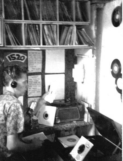
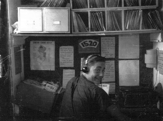
1510 AM On Your Radio Dial with Knight Kit Broadcaster!
|
||||||
