| We are actively seeking
information related to any of the topics presented on this page...
please email info@smecc.org if you can
be of assistance!
Thanks, Ed Sharpe archivist for SMECC
|
||
The following fact sheet is from a memo in the Burroughs Corporation Collection (CBI 90), Product Literature (Box37) at the Charles Babbage Institute for Computer History, Minneapolis, MN.
Back-up
Intercept Control (BUIC) Training and Installation Data 31 January 2010 Robert W. Nelson, CMSgt. USAF Ret.
tells us: During the period between 7 January
1964 and 14 November 1965, I was a TSgt. Team Chief serving in the 2866
Ground Electronic Engineering Installation Agency (GEEIA) Squadron at
Kelly AFB, TX. The Air Force decided it would install
the BUIC II. However, the Air
Force had no computer installation people within the GEEIA organizations. GEEIA was to train the following in
house Air Force Specialties for the installation of the BUIC II Project: 303X1
Radar Repair Technicians I do not recall the exact number of
personnel selected to attend training, since it has been 45 years. But
ultimately there would be 5 man teams consisting of personnel provided by
several GEEIA Squadrons trained then each team would spread out across the
nation to do the installations, perform a 72 hour Hot Check and then turn
the BUIC over to the operating site personnel.
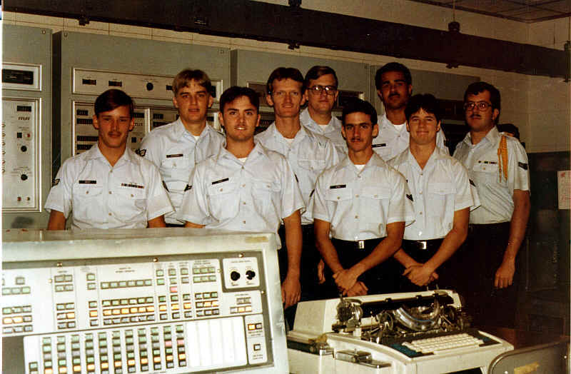
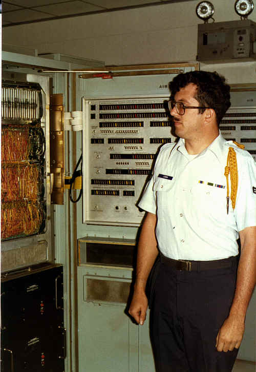
In the BUIC pictured here: From Left to right: 1. Burroughs Civilian Tech Rep, name unk 2. CMSgt Hecker 3. SSgt Scoullar 4. A1C Palmoren 5. unk 6. TSgt Nelson 7. Unk It has been 49 years, can not remember the other names. Our team installed the BUIC II at L.G. Hanscom Field Mass. in June 1965 and the one at Finland, MN in Aug 1965.
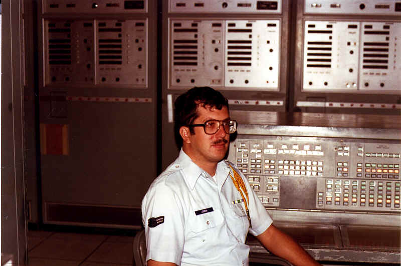
Mike Loewen - BUIC lab in Bryan Hall - Keesler AFB
The BUIC project development was located at the Burroughs "Great
Valley
Labs" facility. The facility was located in a rural area
several miles west of
main Burroughs facility at the intersection of Rts.30 & 252 in
Paoli. The GVL
facility consisted of a secure fenced compound with a main building
complex
consisting of three large Quonset-type structures. At the time
that I worked
at this facility (1964-'69), what I remember seeing of the BUIC
equipment was
located in Building 2. I was an engineering programmer, working on
the
development of the "George" system for Trans World Airlines
and we were
across the hall from the BUIC area (the Quonset's had a main hallway
running
from one end to the other down the middle of the building). We
started out on
the D825 computer but as development continued, our version was
renamed the
"8500". I can remember the large BUIC consoles with the
large, round CRT
screen and the light pen control. Also remember watching non-spec
"games"
being played on the console during late night shift hours :o)
I don't have any
of my old documentation left from those days and can't think of anything
else
that might be of interest relating to the BUIC, BULLSEYE or
RADS military efforts.
E. MacDonald
K.C., MO
I was in the Air Force from 1972
till Sept. 1976 and sometime in 1973 the BUIC III was put into moth
balls. I was a technician on the system working at Charleston AFS in Maine
on the BUIC III.. Lot's of blue neon lights that I with my punch card
program I turned into a 3 million dollar digital clock in the off hours.
A dual CPU computer but not a true dual CPU as it swapped the
running from one CPU to the other... back and forth only one active
at a time. I wish I had photo's but cameras were not allowed on base. I
remember the wind on top of the mountain. I remember the incredible view.
I was transferred to the SLBM DET6 14 MWS and stayed at CHAFS until I was
discharged in 1976. I went there once not too log ago the radomes
are gone the place is just weeds and old buildings behind a chained gate. Former
first term airman of the quarter det 6 14 mws
|
||
|
George Paschetto says:
|
||
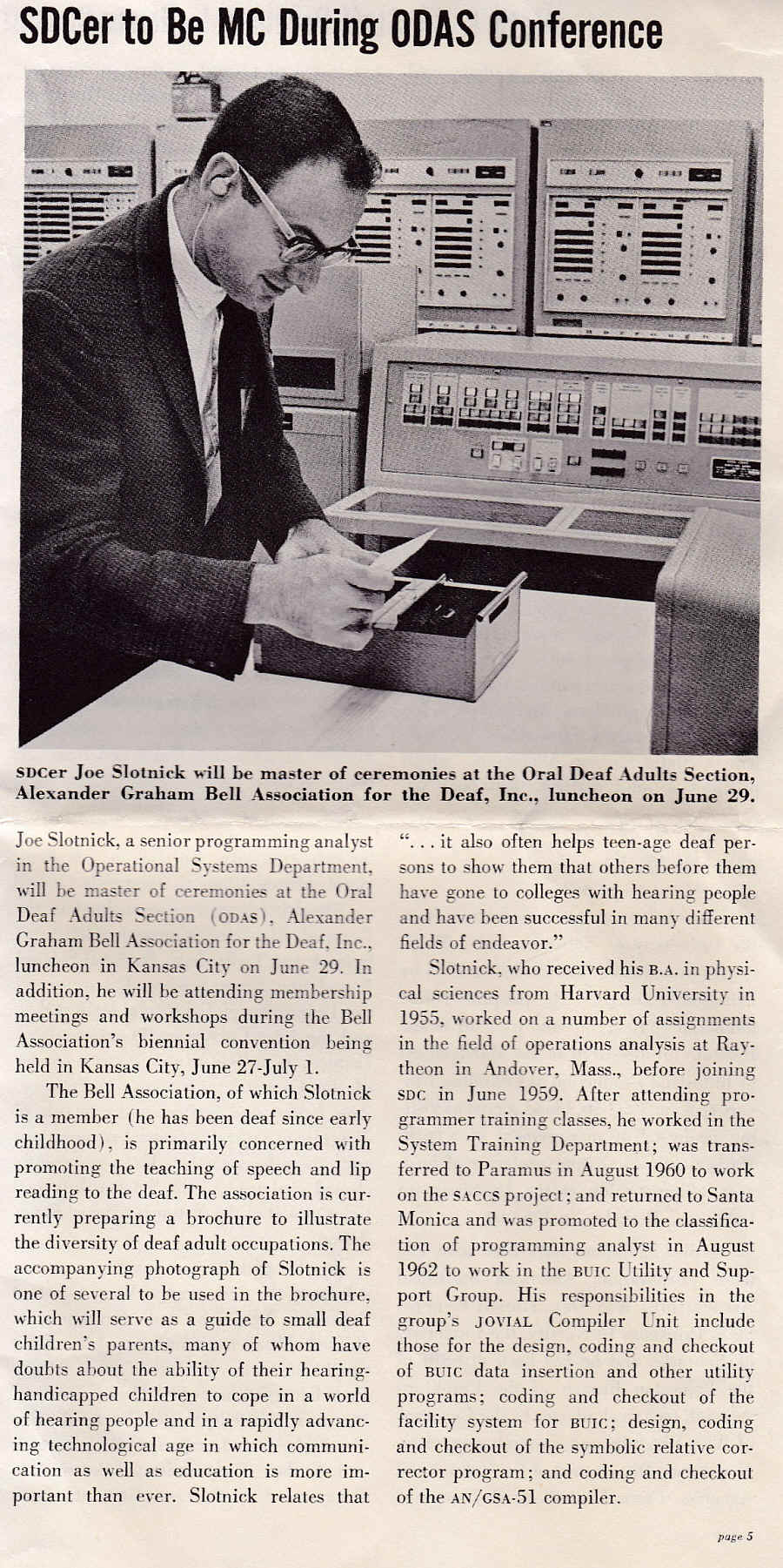
Joe Slotnic tells us "We
finally found the picture I had wanted to send to you,
regarding the story of my interview with SDC and obtaining
employment with them. The date was probably April, 1966,
as the article speaks about me being MC at a luncheon at
the A. G.Bell Convention in Kansas City in 1966. I was a
young 31 years old at that time!"
It was by System Development Corporation and the ad was
looking for computer programmer trainees who could satisfy 5
criteria for employment... I do not remember all 5 criteria
but one of them was "US Citizenship required," and
another was "a suitable mathematical background."
I knew I could satisfy all of them so I took the ad with me
to work the next day, Monday. The ad said that interviews
would be lined up just for two days, Monday and Tuesday. Use
of the telephone (via TTYs and later use of relay services)
was not available for deaf people at that time, that was why
I took the ad with me to work on Monday. (I was working for
Raytheon Manufacturing Corp, and had been working for them
three years. I had started out as a layout draftsman,
pledging with them that I wished to go to night school and
take courses in mechanical engineering. The guy who
recruited me apparently had other ideas for me and hoped I
would become part of an "operations research"
group he was planning to start at Raytheon. To make a long
story short, things did not work out and I ended up being
just a clerical person doing essentially payroll type work.
I had my degree in Physical Sciences that I got from Harvard
in June 1955 and had graduated with nary an idea of what the
heck I wanted to do with my life!) I had our secretary (she
certainly was a great gal and a very cute one too) call the
recruiter for me. She worked hard on him, telling him that I
was a very personable and capable person and that he should
at least give me a chance to come in person and talk with
him. He finally consented to see me at 8am the next morning,
on Tuesday.
There was an ad in the Boston Sunday Globe newspaper
that my first wife noticed (!) and asked me what I thought
about it?
My admiration for the SDC people and working with them was very high
indeed. I remember one quiz where I had the wrong answer for a
question, so I took it up with the instructor. He showed me why I was
wrong, but I asked him to wait, fetched the notebook from the guy I
was taking notes from and pointed out where I got my information. It
turned out that this guy doing the notes was in error himself, but he
had the right answer on his test paper! This gave the instructor a
glimpse into some of my problems - getting the wrong information by
accident and through no fault of my own! They did me a great favor in
assigning me to the Research & Development Dept with programming
work on the "new" IBM 709 computer! Most of the others in
the class were assigned to further work in SAGE. The reason for this,
they said, was that if I had been assigned to advanced SAGE
development with all its needs for instant communications etc I might
not have liked it very much, but doing work either by myself or with a
few others in the 709 environment would be more beneficial for me.
I left SDC 21 years later with quite different feelings. The company
had changed and so had the people within it. It was time for me to
leave, any way. But I had a great 21 years experience with the
company!
Joe Slotnick, SDC Employee #4081.
Added note - And yes I was first deaf programmer at SDC but not first
deaf employee. A deaf girl in Personnel Dept contacted me when she saw
my picture etc in that SDC publication and had been there up to one year
before I joined the company. She was contemplating taking the
programming course and become a programmer. Don't know if she did that
nor do I remember her name!
|
||
|
The
Automatic Message Processing System at the Pentagon was there at the
turn to the 1970 decade. The log entry read, “End of ‘decade’”,
instead of “shift”. Although
it was still a “dual, parallel, fail soft with graceful degradation,
and automatic recovery” system, there were software changes from the
BUIC mission. One
was it didn’t swap master and slave functions automatically by time;
It swapped when either any backup system failure was detected, or either
CPU detected a failure of the other CPU to increment a real time clock
count in memory. The current CPU master could, of course, initiate a
“recovery cycle” of diagnostics for any detected error, peripheral,
or system element. If memory (mine) serves, it was a 99.996 % uptime
system. It failed about once every six months. Sometime(s) this was due
to both CPUs claiming fault in the other. Failure to auto-recover
resulted in many 132 column width pages of memory dump printing loudly
(printer solenoid hammers striking ribbon + paper against a rotating
metal mandrel), followed by a pathetically short last line spit print of
“help”, followed by “Pat” the Burroughs programmer eventually
arriving from PA to analyze the dump. A
few hardware details are: 3 MHZ oscillator, thin film memory, 48 bit
word length, 64K “memory modules” – not pcbs, but ~6’ high X
~3’ wide cabinets. Bryant Drums, disks, tapes, Uptime (& an MDS)
printers, card readers, all in duplicate, except for the card punch. The
push buttons for operators on the message consoles were an alphabet soup
of every “XIA”
agency, and departments, and some individuals near, or at the top of US
government you can imagine, who might need to get a message. That’s
all I have time for right now.
BUIC: Many sites-When
used for North American Continental Defense, the sites Charles Long
ago and far away (but still on planet earth) computers had evolved from
the original tube types. See:
SAGE , BUIC-I [-II, -III], Whirlwind computer, IBM 7090
"Stretch"-history and forebears, Ed Thelen, et al. http://www.radomes.org/museum/buic.html http://www.smecc.org/burroughs_buic_-__an_gsa-51__sage_backup.htm Defense
computer lore from before my time: The earliest North American Continental
defense systems, such as SAGE, sometimes required men with wheeled carts,
which held vacuum tubes, pushing them along the computer's aisles to
replace failed tubes. This happened routinely. The
only tubes I was involved with were from commercial electronics products. As
an original geek, but not quite the fictional Mr. Spock, my very first,
“darling computer”, which could neither make coffee, nor love (nor
kids, etc., etc.), was the Philco S-2000. I mention it, because
it’s architecture had advanced features at the time, such as a
double-length word of 48 bits. Functionally, this really was two, 24 bit
machines operating sequentially. Since memory was slow [ALL COMPUTER
MEMORY FETCHES NOT FROM LOCAL REGISTERS ARE SLOWER-due to bus access and
transfer times- RELATIVE TO CPU EXECUTION SPEEDS, ERGO A PC’S L1, L2,
etc,(Level/Local REGISTER memory caches for the execution Unit)] this
enabled a two-fold speedup in two ways. Doubling memory speed by accessing
two memory words at once, and doubling processor speed by executing two
instructions (~left and then right) before needing to “reload” the
Program Register. Also, UNLIKE IBM’s 7090, and Burroughs’s D825, it
was an ASYNCHRONOUS processor. The architectural engineer’s theoretical
argument went thus: It works near the speed of light, since the logic just
passes electronic signals, and never waits for the “clock” output
pulse of an oscillator. That sounds great, but real-world factors, such as
variations in the rise-and-fall time of early transistors required
accommodation by a gating pulse. This pulse was timed to arrive at the end
of the greatest time it took for any 2N404 transistor to change states,
from conducting (the “on” or binary 0 state) to non-conducting,
and vice-versa. This was the timing requirement for how a 48 bit (bits in
parallel) register word was transferred, or “built-up” by transistors
changing states in parallel. So,
where did the gating ~=(approx. equal to) settling time ~= transfer pulses
come from? They came from three, identical, main CPU, specialized type of
circuits, each called a “single shot”. When I later worked on the SDS
940, and Xerox Sigma 2/3/6/7/9 asynchronous CPU/I-O systems, the single
shots were replaced by “delay lines” with the same function. Thus,
the Synchronous computer designer (IBM, Burroughs D825,
et al, and all PCs) had some counter points, or counter claims: “The
asynchronous system needs and uses pulse timing, so the logic waits
for a pulse anyway; The clock pulses of a Synchronous system are so fast,
that they are everywhere, and the circuitry never needs to wait for
one.” Burroughs’ system designers, however ran into timing problems
with the later 8500, because the pcb’s different foil leads’ lengths
themselves acted as delay lines (and radiative effects) at higher clock
rates. Some circuit chips may have been more sensitive, also. [more
other “stuff” possible later, unless it’s too boring] I’ll
tie it together now: The D825
and the Philco S-2000 had something in common. They had very expensive
operating Control panels. Virtually every CPU register and all memory bits
each had an on-off light. Although the Philco S-2000’s was the size of a
church organ, it was not a system-wide, multi-element status indicator;
One had to figure out what/why there was a malfunction. The D825
had both a front panel with it’s own tri-lead, green, mini neon bulbs$,
and a separate, church organ sized bank of system-wide, multi-element
status indicators. It had red (failed), yellow (suspect with some
diagnostic requirement), and green (good), DUAL bulb-ed (in case one
burned out) indicators for each, and every system device, and processor!
When, rarely, there were many problems, and at Christmas time, when a
special deck of punch-cards was entered, the console was lit up with red,
yellow, and green lights. Via the cards, they were ALL blinking like a
Christmas tree. It was really just a bulb test program. The
D825's original mission was as an air defense computer system, and SAGE
BUIC, like and after SAGE, was for U.S. continental defense. However, it
had a phenomenal (for the time) up-time rating, due to it's proprietary,
and highly specialized, HardWare-S/W
combination. Decades(?) later a company called Tandem specialized in high
up-time systems for commercial markets, banks, etc. More?
A precursor of the Philco S-2000 was an Octal Philco system,
lent/rented/sold-for-cheap to the Israelis for their air defense, and
six-day war. Though I was not involved in that in any way. To clarify, “Doubling memory speed by accessing two memory words at once...” is not to be taken literally. The memory speed wasn’t doubled. Accessing a 48 bit memory once to get two, 24 bit instruction op codes-&-operands, meant that that type of fetch for instruction op codes-&-operands took half the time, by eliminating another, second fetch. AND, two memory words weren’t fetched. Rather, it just equaled double the bit length. Raw data could still be 48 bits long, and require two fetches for, say, an ADD for the two "terms", also called the "addends". --------------------- Philco
1000 computers were used by the Israeli military. See
Appendix B, columns 2 and 5 of the attached system description. Why? This
is the “rare” information that defines it (definition of the code
type) as an octal system. Also, a correction: The prior emailed text should be “...all Memory Address Register bits...”, not “...all memory bits...” Every memory bit was NOT displayed on the console! Charles |
||
|
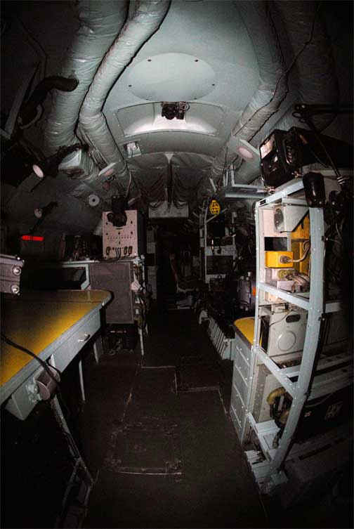
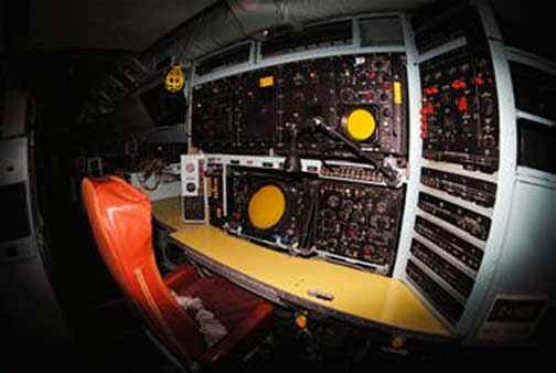
EC-121H out of Otis on Cape Cod, we connected to a
BUIC ground Thanks for sharing this with us James! - Ed# Hi, I flew on the EC-121H out of Otis on Cape Cod, we connected to a BUIC ground site on the outer Cape, between Chatham and Province Town. I have some pics I collected over the years I flew as First Radar Tech doing repairs to the radar systems, in-flight. James Hunter
The data link antenna, steerable, is the small dome directly above, on
top of the fuselage, above "U.S."
It was used to connect BUIC (near Province Town on Cape Cod) and SAGE.
The tall radome above the wing is the height finder, the search radar is
under the fuselage, at the wing.
Really old we had ashtrays! Missions were 10-12 hours over the
Atlantic. Mainly from the Carolinas to Maine.
I flew for about 2 1/2 years and typically pushed up to 100 hours/month
of flight time.
Our mission was to extend the radar coverage off the east and west coasts
and to provide radar coverage to sea level.
The Squadrons were the AEWC 551 at Otis and AEWC 553 in Sacramento.
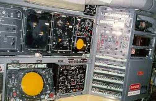
Navigator and Radioman stations
This was the position I usually flew at, 1st Radar Tech, circuit
breakers for the electronics.
We had an alternator dedicated to the electronics on an outboard engine.
The Squadrons were the AEWC 551 at Otis and AEWC 553 in Sacramento.
(AEWC = Airborne Early Warning and Control)
http://en.wikipedia.org/wiki/551st_Electronic_Systems_Wing
history of the 551 AEWC
http://www.dean-boys.com/552/552ndwg.htm
552 AEWC Sacramento plus other info
The also were in Thailand flying over the Gulf of Tonkin, radar covered
all the Vietnamese bases where Migs were based. Some ended up patrolling
between Iceland and Scotland tracking Russian aircraft mainly Bears.
Lots of electronic variants, but the EC-121 series were the radar early
warning aircraft.
|
||
| We are actively seeking
information related to any of the topics presented on this page...
please email info@smecc.org if you can
be of assistance!
Thanks, Ed Sharpe archivist for SMECC
|
||