On
Monday, March 18, 1985, a U.S. federal trademark registration was
filed for SCHWEM
TECHNOLOGY. This trademark is owned by SCHWEM
TECHNOLOGY, INC., PLEASANT HILL , 94523 . The USPTO has
given the SCHWEM
TECHNOLOGY trademark serial number of 73527159.
The current federal status of this trademark filing is CANCELLED
- SECTION 8.
An optically stabilized camera lens system includes an objective
lens mounted to the lens case and an optical train defining an
optical path between the objective lens and a camera image plane.
The optical train includes first a Humphrey prism, second a light
reversing, cube corner element, third a zoom lens. Provision is made
for replacement of the cube corner with a prism and use of a parity
inverting prism such as a Dove or preferably a Pechan to provide an
alternate path. Roll stabilization is provided by coupling the
Pechan, Dove or equivalent parity reversing prism to a gyroscope so
the prism becomes a derotating prism. The derotating prism rotates
about the optical path at half the speed the case rotates about the
optical axis to produce roll stabilization preferred in camera and
video applications. The Humphrey prism is inertially mounted to the
case, using a stabilizer to compensate for small accidental tilt and
pan motions of the case. The tilt and pan stabilizer includes a
Cardan suspension assembly including a first gimbal mounted to the
case, a second gimbal pivotally mounted to the first gimbal and a
precessor biased rotor mounted to the second gimbal. A third gimbal
is pivotally mounted to the second gimbal; the Humphrey prism is
pivotally mounted to the third gimbal. The Cardan suspension
assembly provides a gyroscopically stabilized mount for the third
gimbal.
Inventors:
Alvarez; Luis W.
(Berkeley, CA), Schwemin;
Arnold J. (Danville, CA)
Primary Examiner: Punter; William H. Attorney, Agent or Firm:
Townsend and Townsend
Claims
We claim:
1. A lens system for use with a camera having an image plane
comprising:
a case;
an objective lens forming a first optical element mounted to the
case for receipt of light along an optical axis; and
an optical train defining an optical path within the case between
the first optical element and the image plane, said optical train
comprising:
a second reflecting and displacing optical element positioned along
the optical path following the first optical element, said second
optical element arranged and adapted to redirect the light entering
the second optical element from a first path segment of the optical
path to a second, laterally spaced apart path segment of the optical
path to form a first image along said second path segment;
means for inertially mounting said second optical element to said
case to compensate for small accidental motions of the case so the
first image is a stabilized image;
a third cube corner reflecting optical element mounted within said
case following the second optical element, said corner cube optical
element arranged and adapted to relay light from said second optical
element to a third, laterally spaced apart path segment of said
optical path;
said optical train arranged and adapted to relay light along said
optical path from said third optical element to form a second image
at the image plane; and
a zoom relay lens assembly mounted within the case and following the
third optical element.
2. A lens system for use with a camera having an image plane
comprising:
a case;
an objective lens mounted to the case for receipt of light along an
optical axis forming a first optical element; and
an optical train defining an optical path within the case between
the first optical element and the image plane, said optical train
comprising:
a second reflecting and displacing optical element positioned along
the optical path following the first optical element, said second
optical element arranged and adapted to redirect the light entering
the second optical element from a first path segment of the optical
path to a second, laterally spaced apart path segment of the optical
path to form a first image along said second path segment;
means for inertially mounting said second optical element to said
case to compensate for small accidental motions of the case so the
first image is a stabilized image;
a third optical element comprising two reflecting surfaces mounted
within said case following the second optical element, said third
optical element arranged and adapted to relay light from the second
optical element to a third, laterally spaced apart and reversed path
segment; and
a fourth optical element including a zoom relay lens assembly
mounted within the case and following the third optical element; and
a fifth optical element comprising a parity inverting prism having
reflective surfaces arranged and adapted to relay light along said
optical path from said third optical element to form a second image
at the image plane having even parity.
3. The lens system of claim 2 and wherein said parity inverting
prism is a Pechan prism.
4. The lens system of claim 2 and wherein said prism assembly is a
Dove prism.
5. A lens system for use with a camera having a image plane
comprising:
a case;
a first optical element mounted to the case of receipt of light
along an optical axis;
an optical train defining an optical path within the case between
said first optical element and the image plane, said optical plane
comprising:
means for stabilizing to said image plane an image received through
said optical train;
a derotating prism mounted to said case for pivotal movement about
said optical path;
a roll stabilizing gyro mounted to the case, said gyro including a
gimbal pivotally mounted to said case for movement about a gimbal
axis parallel to said optical axis, a rotor pivotally supported by
said gimbal to spin about a gyro axis, the gyro axis being oriented
in a direction other than parallel to said optical axis; and
means for operably coupling the gyro and the derotating prism to
rotate said derotating prism at one-half the gimbal motion to obtain
stabilization of an image.
6. The invention of claim 5 and wherein said derotating prism
comprises a Pechan prism.
7. A camera lens system comprising a case defining an optical path
for receipt of light along an optical axis to an image plane; an
objective lens, mounted to the case and
an optical train mounted within the case comprising:
a reflecting and displacing optical element positioned along the
optical path following the objective lens;
a reversing and displacing optical element positioned along the
optical axis, following said reflecting and displacing optical
element, the reflecting and displacing optical element being
arranged and adapted to laterally offset and reverse the direction
of light from the reflecting and displacing optical element; and
means for inertially mounting said reflecting and displacing optical
element to the case so as to maintain an original angular
orientation with respect to the optical axis in response to small
tilts and hand movements of the case, said means for inertially
mounting including a Cardan suspension system including first and
second gimbals and a rotor, said first gimbal mounted to the case
for pivotal movement about a first axis, said second gimbal mounted
to said first gimbal for pivotal movement about a second axis, said
rotor mounted to said second gimbal for rotation about a third axis;
means for restoring said rotor as mounted to said first and second
gimbals to a preselected position of excursion of each of said first
and second gimbals to enable maximum excursion of said rotor
relative to the case;
a third gimbal pivotally mounted to the second gimbal for rotation
about a fourth axis;
said reflecting and displacing optical element being mounted to said
third gimbal for pivotal movement about a fifth axis; and
said third gimbal and said reflecting and displacing prism biased to
a preselected position of excursion of said third gimbal and said
reflecting and displacing prism and damped sufficiently to
substantially inhibit vibrations above a chosen frequency from
reaching the optical element.
8. An image position stabilizing assembly comprising:
a Cardan suspension assembly including:
a first gimbal pivotally secured to a base for pivotal movement
about a first axis;
a second gimbal mounted to said first gimbal for pivotal movement
about a second axis; and
a rotor rotatably mounted to said second gimbal for rotation about a
third axis;
means for restoring said rotor to a preselected orientation with
respect to said case whereby said first and second gimbals are
predisposed for excursion relative to said case relative to said
base;
a reflecting and displacing optical element; and
a low frequency mechanical bandpass filter mounting means for
mounting said reflecting and displacing optical element to said
second gimbal, said low frequency mechanical bandpass filter
including a third and fourth gimbals mounted on respective fourth
and fifth axes.
9. An optical element stabilizer comprising:
a case;
a Cardan suspension system including first and second gimbals and a
rotor, said first gimbal mounted to the case for pivotal movement
about a first axis, said second gimbal mounted to said first gimbal
for pivotal movement about a second axis, said rotor mounted to said
second gimbal for rotation about a third axis;
means for restoring said rotor to a preselected position relative to
said case to dispose said first and second gimbals for excursion
relative to said case;
a third gimbal pivotally mounted to said second gimbal for rotation
about a fourth axis;
reflecting and displacing prism mounted to said third gimbal for
pivotal movement about a fifth axis; and
said third gimbal and said prism biased to respective home positions
and damped sufficiently to substantially inhibit vibrations about a
chosen frequency from reaching said optical element.
10. The stabilizer of claim 9 wherein said chosen frequency is about
2 Hz.
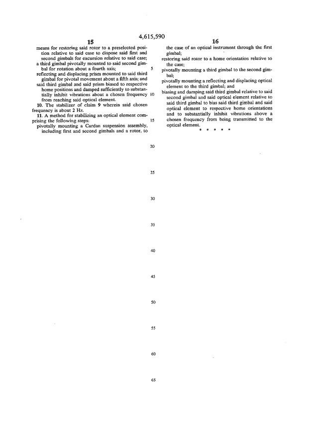
11. A method for stabilizing an optical element comprising the
following steps:
pivotally mounting a Cardan suspension assembly, including first and
second gimbals and a rotor, to the case of an optical instrument
through the first gimbal;
restoring said rotor to a home orientation relative to the case;
pivotally mounting a third gimbal to the second gimbal;
pivotally mounting a reflecting and displacing optical element to
the third gimbal; and
biasing and damping said third gimbal relative to said second gimbal
and said optical element relative to said third gimbal to bias said
third gimbal and said optical element to respective home
orientations and to substantially inhibit vibrations above a chosen
frequency from being transmitted to the optical element.
Description
BACKGROUND OF THE INVENTION
1. Field of the Invention
This invention relates to the optical stabilization of images
provided the recording surface of a hand-held video or film camera.
More particularly, the invention relates to an optically stabilized
zoom lens suitable for use with conventional hand-held cameras in
lieu of conventional removable zoom lens.
2. Summary of the Prior Art
Stabilized optics using a reflecting and displacing prism, disclosed
in U.S. Pat. No. 3,475,073, issued on Oct. 28, 1969 to William E.
Humphrey, are known. The prism disclosed in this patent, hereinafter
sometimes referred to as the Humphrey prism, provides optical
stabilization against certain types of inadvertent movements of the
instrument. This optical stabilization is achieved by the Humphrey
prism, when used with an objective lens system, providing a
stabilized image at a fixed location relative to the lens case. The
Humphrey patent also discloses other reflecting and displacing
optical elements, for example one using three mirrors, which
together with the Humphrey prism are hereinafter collectively
referred to as Humphrey-type optical elements.
Because of this stabilization property, Humphrey prisms have been
used in gyroscopically stabilized optical devices. For example, one
such device has been sold by Mark Systems of Cupertino, Calif. under
the trademark MARK 1610. This device, which is a mono-binocular,
uses a two degree of freedom gyroscope, commonly referred to as a
Cardan suspension, to support the prism. This type of suspension, in
which the prism is rigidly secured to one of the gimbals, helps to
stabilize the viewer's image since small movements of the
mono-binocular case will not affect the gyrostabilized prism.
Although this instrument provides a stabilized image for the viewer,
the resultant image is subject to high frequency vibrations, such as
those produced by the spinning rotor of the gyroscope. The Humphrey
U.S. Pat. No. 3,475,023 patent acknowledges the zoom lens assemblies
and relay optics may be used with the prism stabilizing scheme
therein disclosed. It does not disclose how such systems are
optimized for practical use. Indeed, despite attempts to utilize
these technology in the past, commercial success has not been
achieved.
Devices that can stabilize the line of sight of an ordinary motion
picture or video camera by stabilizing the camera itself have been
in use for many years. These devices may employ either a gyro system
or a greatly increased moment of inertia to accomplish such
stabilization. For mechanical reasons such systems are large, heavy
and expensive, and are therefore most often rented for special
occasions, such as the production of documentaries, commercials,
etc., where the picture-making can be scheduled at some
predetermined and schedulable time in the future.
Electronic news gathering (ENG) is an increasingly important segment
of the television industry. Even a casual review of a single week of
TV national network newscasts will convince the viewer that
fast-breaking news reporting of such events as airplane hi-jackings,
riots, accidents, natural disasters and other such scenes shot from
helicopters, while in a moving car, etc., do not have the benefit of
image stabilization. If the TV networks were offered footage of
ordinary news events with such glaring technical defects, they would
reject them as being hopelessly amateurish. But because of their
newsworthiness, these very unsteady shots are shown in spite of
their obvious technical faults.
SUMMARY OF THE INVENTION
The present invention provides a camera, such as a video or motion
picture camera, with an optically stabilized lens system, preferably
a zoom lens system. The optically stabilized camera lens system
includes an objective lens mounted to the lens case and an optical
train defining an optical path between the objective lens and an
image surface of the camera. The optical train includes a
Humphrey-type reversing and displacing optical element, preferably a
Humphrey prism, following the objective lens, a light reversing and
displacing optical element following the Humphrey-type optical
element which redirects the light from the Humphrey element to a
zoom lens assembly; the zoom lens assembly provides an image to the
image surface of the camera tube. The Humphrey prism is inertially
mounted to the case to be stabilized in tilt and pan to compensate
for small accidental motions of the case.
Two optical path embodiments are shown of the light reversing and
displacing optics to impart conventional camera directionality to
the lens system. First a cube corner may be used. Secondly, a
displaced roof reflecting assembly may be used in combination with a
parity inverting prism, such as a Dove, or more preferably a Pechan.
The reversing and displacing optical element is preferably a cube
corner. In lieu of a cube corner the optically equivalent
combination of a right angle prism and an Amici roof prism can be
used. The cube corner uses three reflections to reverse and displace
the light path while flipping the image upside down. The right angle
prism bends the light path 90.degree. while the Amici roof prism
provides two reflections while bending the light 90.degree. and
flipping the image upside down, A first stabilized image is provided
by the Humphrey-type optical element at or near the first reflective
surface of the cube corner. The total number of reflections, three
within the Humphrey prism and three within the cube corner, being an
even number, maintains even parity of the image. This is necessary
to keep a lower case p from looking like a lower case q. The light
from the cube corner then passes through the zoom optics which
focuses a second image at the image plane of the camera tube with
proper parity but upside down, as is required for conventional video
cameras.
The cube corner is preferably constructed so there is no overlap
between the reflection surfaces. This is significant since it
greatly increases the allowable angular manufacturing tolerances
allowable from about .+-.2-3 arc seconds for an Amici roof plus
right angle prisms to about .+-.10-20 arc minutes for the cube
corner with non-overlapping reflection surfaces. This makes the cost
of the cube corner significantly less than that of the amici plus
right angle prism combination.
In some cases, such as with binoculars or other direct viewing
devices, it is not desired to flip the image upside down. In those
cases a penta prism can be used with a right angle prism as the
reversing and displacing element. The penta prism bends the light
90.degree. using two reflecting surfaces so the total number of
reflections in such reversing and displacing element is three, just
like with the cube corner.
In lieu of using the cube corner as the reversing and displacing
optical element, one can use either two angled mirrors or two right
angle prisms. If this is done, however, an odd number of total
reflections (five) are produced so parity is lost. This can be
remedied by inserting a prism, such as Pechan or Dove prism, along
the optical path. The prism has an odd number of reflecting surfaces
(five for the Pechan and one for the Dove) so even parity is
restored. Also the prism can be oriented to either flip the image,
as is normally required, or leave it erect.
Adding a prism provides an unexpected advantage for the user. This
is so because derotating prisms, apart from having an odd number of
reflections, rotate an image passing through them at twice the speed
at which they are rotated. Although the optical element stabilizer
stabilizes the Humphrey prism against small, inadvertent movements
in tilt and pan, known as pitch and yaw in aeronautical terms, since
the rotor axis is necessarily parallel to the optical axis, the
image provided to the image surface of the camera tube is not
stabilized for roll about the optical axis. Thus, adding a prism not
only eliminates the need for an Amici roof prism but also allows the
image to be roll stabilized--a distinct advantage for video and film
cameras, but not for direct viewing devices. A prism having this
characteristic will hereinafter be referred to as a derotating
prism.
The derotating prism is mounted to the case to pivot about a portion
of the optical path passing through it. The derotating prism is
operably coupled to a gyro having a gimbal mounted to the case to
pivot about an axis parallel to the optical axis. The axis of the
gyro's rotor is in a direction other than parallel to the optical
axis and preferably about 90.degree. to that axis. The coupling is
configured to rotate the derotating prism at half the speed at which
the gimbal rotates relative to the case. Thus rolling the lens case
about the optical axis, since the gyro rotor tends to remain in
position, causes the gimbal to move relative to the case. The image
provided the image plane remains stationary relative to the camera
as the derotating prism is rotated at one-half the speed at which
the camera and lens rolls about the optical axis.
The Humphrey prism is stabilized in tilt and pan by an optical
element stabilizer. The optical element stabilizer also isolates the
Humphrey prism from higher frequency vibrations, caused by the
gyroscope motor or exerted on the case of the instrument, while
remaining light and compact for ease of use and interchangeability
with conventional camera lenses. The optical element stabilizer
includes a two degree of freedom gyroscope, termed a Cardan
suspension assembly, and a Humphrey prism isolation assembly which
mounts the Humphrey prism to the Cardan suspension assembly. The
isolation assembly includes a gimbal to which the Humphrey prism is
pivotally mounted and which is itself pivotally mounted to a gimbal
of the Cardan suspension assembly. The Cardan suspension assembly
provides a gyroscopically stabilized mount for the Humphrey prism
isolation assembly. The Humphrey prism isolation assembly acts as a
mechanical low pass filter isolating the Humphrey prism from higher
frequency vibrations, especially those produced by the rotor,
bearings and other motor components.
The reader will realize that the inner gimbal helps accommodate
balancing imperfections in the gimbal system. If one could be sure
that the balance of the rotor and gimbal assembly mounting the
Humphrey prism could be almost perfect after the instrument had been
subject to periods of rough handling, the inner gimbal system would
not be needed. This inner gimbal system is present to avoid the
necessity of frequent rebalancing of the rotor. Additionally, the
isolation gimbal system can cut down on the expense of the precise
balancing job that would otherwise be required. It is important to
understand that the isolation gimbal system is not essential to the
working of this disclosure.
A precessor is used to bias the rotor so that the rotor axis tends
to remain parallel to the optical axis of the instrument. The
isolation assembly gimbal and the Humphrey prism are biased to their
respective neutral positions by springs and dampers. The spring
biasing is preferably provided using opposed magnets while damping
is provided, in the preferred embodiment, using a threaded pin
extending from one element into viscous material within a cavity in
the other element, thus creating a dashpot. The biasing and damping
provided by the isolation assembly is chosen to substantially damp
out all the vibrations transmitted to the optical element having a
frequency above about 2 Hz. The biasing and damping of the isolation
assembly and the precessor is chosen to allow the optical instrument
to be smoothly panned while eliminating vibrations from the rotor
and external vibrations exerted on the lens case. The optical
stabilizer of the invention can be used with various optical
instruments, such as a hand held video camera and a hand held
mono-binocular. It may also be used to help stabilize a still camera
using a high power telephoto lens.
Permanent magnet precessors have the inherent characteristic that
any slight angular deviation of the rotor axis from the optical axis
will be countered by the precessor tending to realign the two axes.
It is usually desirable that the precessor have what is termed a
flat spot. That is, the precessor should be constructed so that no
precession takes place unless the angular deviation is above some
generally small angle, termed the flat spot angle, such as 1/2
degree. With a precessor having such a flat spot the image from the
optical instrument appears like it was taken on a tripod.
The precessor has a relatively long time constant so that the
corrections it makes to the gyro axis are rather slow. This will
produce, with, for example, a hand-held video camera, an image which
tends to oscillate slowly right and left, and to a lesser degree up
and down. Using the same signals from the sensors which are used to
control the torquers, an indication can be provided on the camera's
CRT viewer of any deviation of the gyro axis from the optical axis.
This can be accomplished by superimposing two marks on the CRT
viewer screen, one representing the gyro axis and the other the
optical axis. This will allow the user to observe oscillation of the
camera case in pitch and yaw. To keep the picture steady the user
would just keep the optical axis (corresponding to the case's
orientation) oscillating on either side of the gyro axis. Since the
precessor is slow acting, only when the oscillations are, for
example, about a point to the right of the gyro axis will the gyro
axis precess to the right. In a moving picture viewfinder similar
information could be presented in various ways, such as using arrays
of light emitting diodes or crossed meter pointers. It should be
noted that this aspect of the invention can be provided in
conjunction with the sensors and torquers used to provide the flat
spot in the precessor. However, this pitch and yaw deviation
information can be had independently of providing a flat spot
precessor. It will be appreciated that roll information could be
provided in a similar manner.
The tilt and pan stabilizing gyroscope rotor acts as the rotor of a
DC brushless motor. The rotor includes numerous permanent magnets
imbedded about its periphery with the orientation of the poles
alternating. The motor stator includes at least one electromagnet
having poles placed opposite the permanent magnets of the rotor. The
motor circuitry includes a Hall effect detector which senses the
position of the moving permanent magnets. The movement of the
magnets past the Hall effect detector causes the motor circuitry to
reverse the polarity of the electromagnets, thus driving the rotor.
The rotor is provided with a wind shield, which is mounted to the
second gimbal. The wind shield acts as a shroud surrounding most of
the motor. The wind shield serves dual functions. First, it lowers
the resistance of the rotor to spinning by keeping the rotor from
pumping air from its interior portions to its exterior portions.
This greatly extends the life of the batteries which are usually
used to power the motor. Second, the wind shield effectively
eliminates turbulent air currents on the prism within the instrument
case which could otherwise cause it to wobble or vibrate.
A pair of caging mechanisms are provided to protect the optical
stabilizer when not in use. One of the caging mechanisms is used to
lock the windshield in place. Since the windshield is mounted to the
gimbal of the Cardan suspension assembly to which the rotor is
journaled, locking the windshield in place locks the Cardan
suspension assembly in place also. The other caging mechanism
includes a pivoting member which engages the Humphrey prism to keep
it from pivoting. The Cardan suspension assembly caging is typically
released first while the Humphrey prism is released second.
Two primary constraints are placed on the design of the optical path
to enable the lens system to be used as a replacement for
conventional zoom lenses. First, the image provided the image plane
of the video or film camera, must have correct parity so that a p
does not look like a q. This, as discussed above, is accomplished by
providing an even number of reflections along the optical path.
Second, the portion of the optical path at the image plane must be
such to allow the camera body to be held in its conventional manner.
Both conventional video cameras and conventional film cameras are
made so the image plane is perpendicular to the optical axis and the
optical path at the image plane is in the same direction as the
optical axis. The Humphrey prism provides a stabilized first image
at a point along the optical path following the Humphrey prism. If
the first image were at a photo sensitive surface, the camera would
appear to be pointing backwards, quite unacceptable for retrofit
operations. To enable this stabilized first image to be used with
conventional cameras alignment, the optical path must be reversed so
that the optical path at the final image plane is parallel to and in
the same direction as the optical axis. To do so, a reflecting and
displacing optical element is mounted within the lens case following
the Humphrey prism to intercept the optical path adjacent the first
image and relay this image to the sensitive surface, which is
typically in a video camera.
The present invention thus provides the user of mechanically
unstabilized, typically shoulder mounted or hand-held cameras a
stabilized zoom lens system which is light enough and inexpensive
enough to be carried around and used when needed. The stabilized
lens system is configured to be attachable to standard handheld and
shoulder mounted cameras in the same manner in which conventional
unstabilized zoom lenses are mounted. The present invention thus
provides a stabilized zoom lens which can easily and quickly be
substituted for a conventional unstabilized zoom lens. The present
invention is particularly adaptable for use in electronic news
gathering to provide a quality of picture which has heretofore not
been commercially feasible, as it has been in the shooting of
commercials, etc., which can be scheduled to permit the renting of
the very expensive prior art mechanical stabilizers of the whole
camera.
Other features and advantages will appear from the following
description in which the preferred embodiments have been set forth
in detail in conjunction with the accompanying drawings.
BRIEF DESCRIPTION OF THE DRAWINGS
FIG. 1 shows the optically stabilized camera lens system of the
invention used with a conventional video camera.
FIG. 2 is a simplified isometric view of the elements comprising the
optical path of the corner cube versions of this invention between
the objective lens and the camera tube of the lens system of FIG. 1.
FIG. 2A is a front view of the cube corner assembly illustrating the
preferred sequential use of each of the three surfaces of the corner
cube.
FIG. 3 is a simplified isometric view of a second embodiment of the
lens system of FIG. 1 including a Pechan prism adapted as a roll
stabilizer positioned along the optical path between the zoom optics
and the camera tube.
FIG. 4 is a schematic representation of the optical element
stabilizer of the invention.
FIG. 5 is an exploded isometric view of the optical stabilizer of
the invention illustrating the gimbals, optical element and rotor.
FIG. 6 is a partial cross-sectional plan view of the optical element
stabilizer of FIG. 5 including the motor stators mounted to a
printed circuit board, a wind shield device and a precessor.
FIGS. 7, 8A and 8B show the Humphrey prism and gyro caging
mechanisms.
DETAILED DESCRIPTION OF THE PREFERRED EMBODIMENTS
Referring now to FIGS. 1 and 2, an optically stabilized camera lens
system 2 is shown mounted to a conventional video camera 4. Lens
system 2 includes a lens case 6 within which various optical
elements described below are mounted. An objective lens assembly 8
is mounted to case 6 to accept light from object 0 along an optical
axis 10. An optical path 12 is defined within case 6 between
objective lens assembly 8 and an image plane 14 at the end of a
camera tube 16. Lens system 2 is mounted to camera tube 16 as a
replacement for a conventional zoom lens. A number of optical
elements, specifically a Humphrey prism 18, a reflecting, inverting,
and displacing optical element 20 and a zoom lens assembly 22, are
positioned along optical path 12. Element 20 is a cube corner,
although other optically equivalent elements could be used as well.
Objective lens assembly 8 includes first, second and third objective
lenses 24, 26 and 28, all of conventional design. Humphrey prism 18
is inertially stabilized within case 6 with respect to inadvertent
tilt and pan movements; this aspect is described in detail below
with reference to FIGS. 4 to 7. Humphrey prism 18 follows objective
lens assembly 8 along a first path segment 30 of optical path 12.
The image of object 0 is reflected within Humphrey prism 18 three
times so that the first image I-1 along a second path segment 32 no
longer has even parity.
Reflecting, inverting and displacing optical element 20 follows
Humphrey prism 18 along second path segment 32. Element 20 is
fixedly mounted to case 6 and includes three mutually perpendicular
reflecting surfaces 40, 42, and 44. A fixed lens 34 is mounted to
the front face 36 of cube corner 20. Cube corner 20 is positioned so
that surface 40 intersects optical path 12 generally at or behind
where first stabilized image I-1 lies. U.S. Pat. No. 3,475,023
discusses how the Humphrey prism 18 provides an image stabilized
with respect to the case.
Three reflections occur within cube corner 20 by virtue of its shape
as the image progresses from second path segment 32 to a third path
segment 48. Third path segment 48 extends from optical element 20 to
image plane 14 of camera tube 16. The three reflections within
optical element 20 also flip the image of object 0 upside down.
Mounted within case 6 along path segment 48 is zoom lens assembly
22. Assembly 22 is constructed and movably mounted within case 6 in
a conventional manner and thus will not be described in detail. Zoom
lens assembly 22 is shown in three different zoom positions 50, 52
and 54. Zoom position 50 is the high, 300 mm focal length position,
position 52 is an intermediate focal length position and zoom
position 54 is a low, 60 mm focal length position. An iris diaphragm
is positioned at point 56 and a backing lens 58 is positioned along
third path segment 48 following zoom lens assembly 22 to provide an
appropriate second image I-2 of object 0 at image plane 14.
Assembly 22 is a zoom relay lens as contrasted with a conventional
zoom lens. A conventional zoom lens takes parallel light, from a
distant image, and focuses it at a film gate with varying equivalent
focal lengths. A zoom relay lens takes light from a nearby object
(the image formed by the objective lens) and focuses it at an image
plane (on the camera tube) with varying magnification. Therefore,
lens system 2 is quite unconventional, for camera use.
To obtain correct image parity, an even number of reflections along
optical path 12 are needed. This is achieved by three reflections
within Humphrey prism 18, and three reflections within cube corner
20. The image is turned upside down within cube corner 20, to
compensate for the fact that the relay lens system inverts the
image, so that the image provided image plane 14 is upside down as
is necessary for conventional video cameras that use interchangeable
lenses.
Referring to FIG. 3, a second optically stabilized camera lens
system 100 is shown. Lens system 100 is similar to lens system 2 and
includes an objective lens assembly 8, a Humphrey prism 18, a
reflecting and displacing optical element 101, a zoom lens assembly
102 (shown at a high focal length position), a backing lens 58 and a
derotating prism assembly 104 positioned between backing lens 58 and
the image plane 120 of a camera tube 122. These elements are
positioned along an optical path 123.
Derotating prism assembly 104 includes a conventional derotating
prism 112 mounted between a negative lens, 111, and a positive lens,
115, arranged to lengthen the optical path, but keep the effective
focal length the same as it would be without the presence of the
derotating prism assembly. As shown, prism 112 axis is at a right
angle to the main optical axis 10, but it could equally well be
parallel to that optical axis. Negative lens 111 is mounted to a
first right angle prism 110, which redirects light along optical
path 123 at a right angle from third path segment 48 to a fourth
path segment 116. Positive lens 115 is mounted to a second right
angle prism 114 which bends path 123 along a fifth path segment 118
and to the image surface 120 of a camera tube 122.
Lens system 100 uses a Pechan, prism as derotating prism 112.
Although a Dove prism can be used as well, a Dove prism only works
in parallel light and its physical length, for a given aperture, is
considerably greater than that for a Pechan prism. The Pechan prism
is therefore preferred.
Incorporating a derotating prism along optical path 123 eliminates
the need for the cube corner 20 of the embodiment of FIG. 2, which
is relatively expensive. If the optics are to be used where it is
not desired to have an inverted image, the derotating prism would
simply be rotated 180.degree. about optical axis 12. Also, any
initial adjustment or setting of the horizon angle can be
accomplished by an initial adjustment of derotating prism 112.
Derotating prism assembly 104 is mechanically coupled to a roll
stabilizing gyro 106 by a mechanical coupling assembly 108. Roll
stabilizing gyro 106 includes a rotor 124 mounted for rotation about
a generally vertical first, rotor axis 126 to a gimbal 128. Gimbal
128 is pivotally mounted to lens case 6, illustrated schematically
in FIG. 3, for rotation about a horizontal third axis 134. Axis 134
is collinear with optical axis 10 so that when camera 4 plus lens
case 6 is rotated or rolled about optical axis 10, the support
shafts 136, 138 mounting gimbal 128 to case 6 rotate a like amount.
This provides a basis upon which mechanical coupling assembly 108
can rotate derotating prism 112 about fourth path segment 116 at
one-half the speed of rotation of lens system 100 about optical axis
10.
Mechanical coupling assembly 108 includes a first pulley 140 coupled
to a second pulley 142 by a flexible wire 144 which is guided
through a 90.degree. turn by a pair of guide pulleys 146, 148.
Second pulley 142 surrounds derotating prism 112 and mounts prism
112 within the interior of second pulley 142. Second pulley 142 is
mounted to case 6 by three evenly spaced apart support rollers 150
which engage the circumference of pulley 142, or equally well, a
large diameter ball bearing system. Support rollers 150 are
themselves mounted to case 106. Pulley 140 is half the diameter and
thus half the circumference of pulley 142 so that a 2 to 1 speed
reduction occurs between a rotational movement of shaft 138 (and
thus pulley 140) and pulley 142 (and thus prism 112). This
compensates for the fact that the rotating prism 112 tends to rotate
the image twice the speed at which it is rotated. Thus pivotal
movement of camera 4 about axis 10, otherwise known as roll, is
compensated for by derotating prism 112, coupling assembly 108 and
gyro 106, collectively known as the roll stabilizer 151. A spring
(not shown) can be used along wire 144 to eliminate backlash.
Referring now to FIG. 4, a preferred embodiment of an image position
stabilizing assembly 202, is illustrated schematically. Assembly 202
will be described in some detail in that it comprises a significant
aspect of the invention. Assembly 202 includes broadly a Cardan
suspension assembly 204, a prism isolation assembly 211 and Humphrey
prism 18. Cardan suspension assembly 204 includes a first gimbal
206, a second gimbal 208 and a rotor 210. Prism isolation assembly
211 includes a third gimbal 212 mounted to second gimbal 208,
Humphrey prism 18 being pivotally mounted to gimbal 212. Stabilizer
202 is used to aid image stabilization of the first image I-1, shown
in FIG. 2.
Referring also to FIGS. 5 and 6, first gimbal 206 is mounted to case
6 to pivot about a first, vertical axis 218. Second gimbal 208 is
mounted within first gimbal 206 to pivot about a second, horizontal
axis 220. Rotor 210 is mounted to a central bearing block portion
224 of second gimbal 208 by a rotor shaft 225 for rotation about a
third, horizontal axis 222. Cardan suspension assembly 204, which is
supported by case 6, is used to gyroscopically support prism
isolation assembly 211 and prism 18 therewith.
Third gimbal 212 is pivotally supported between extensions 226, 227
to pivot about a fourth axis 228. Prism isolation assembly 211
includes a Z-shaped support 230 and a pair of end plates 232. Plates
232 are secured to prism 18 by a suitable adhesive and to Z-shaped
support 230 by screws 233. Prism 18 is pivotally mounted to third
gimbal 212 through plates 232 so prism isolation assembly 211 and
prism 18 pivot about a fifth, vertical axis 234.
As indicated in the figures, first, second and third axes 218, 220
and 222 are nominally orthogonal axes and intersect at a first point
236 (see FIG. 6). As used in this application nominally orthogonal
means that the axes are orthogonal when the stabilized components
are in their neutral positions shown in the figures. Fourth and
fifth axes 228, 234 intersect third axis 222 at a second point 238
and are also nominally orthogonal. Second point 238 coincides with
the combined center of gravity of prism 18 and prism isolation
assembly 211 so that prism 18 tends to remain in its neutral
position shown in the figures. The center of gravity of image
stabilizing assembly 202 is preferably coincident with first point
236 so assembly 202 is balanced about first axis 218.
Rotor 210 has an enlarged outer region 240 which contains a series
of magnets 241 with the north and south poles of the magnets
alternating. Rotor 210 is mounted to rotor shaft 225 which passes
within bearing block portion 224 of second gimbal 208. Rotor 210
acts as the rotor element for a brushless DC motor 244. The
components comprising motor 244, excepting rotor 210, are mounted to
a circular printed circuit board 246 which itself is mounted to
second gimbal 208 by a pair of stand offs 248. A dish-shaped wind
shield 249 is mounted to the peripheral edge 251 of printed circuit
board 251. Shield 249 and board 251 prevent rotor 210 from creating
turbulent air currents within the instrument, which would degrade
the stabilization. The use of wind shield 249 also reduces the
energy required to drive rotor 210. This is quite important because
it extends the life of the batteries, commonly used to power motor
244, by a significant factor.
Motor 244 uses a Hall effect device which senses the position of the
passing magnets 241. The motor stator 250 is energized and
deenergized according to the output of the Hall effect device to
alternately attract and repel magnets 241. This type of motor, which
is well-known, causes rotor 210 to spin so that Cardan suspension
assembly 204 provides a two degree of freedom gyroscopically
stabilized support structure for prism isolation assembly 211 and
prism 18.
It is desired to maintain third axis 222, that is the spin axis of
rotor 210, parallel with the optical axis 10, shown in FIGS. 1, 2
and 6, of the optical instrument with which stabilizer 202 is used.
To do this, a precessor 252 is used. Precessor 252 includes a main
iron shaft 254 mounted to case 6 through an H-shaped mounting plate
255, shown in FIGS. 6 and 8A, and extends through a central opening
256 of a convex, circular copper disc 258. Disc 258 is supported by
a circular extension 260 of rotor 210. A circular iron shoe 264 is
mounted to shaft 254 on the other side of opening 256. A magnet 266
is mounted to an enlarged end 262 on the other side of opening 256
to provide a magnetic field 268 within opening 256.
Rotor 210, once spinning, tends to gyroscopically maintain its
position against tilt and pan movements. However, during use the
orientation of case 2 is changed as camera 4 is pointed in different
directions. This movement of case 2 causes copper disk 258 to move
into magnetic field 268. Since central opening 256 is no longer
centered within field 268, a restoring torque is exerted on copper
disk 258 tending to realign rotor 210 so third axis 222 once again
becomes aligned with main viewing axis 250. Precessor 252 acts to
restore the gyro axis parallel to the case axis because of the eddy
current drag on disc 258 produced as the spinning disc passes
through magnetic field 268. Thus, precessor 252 causes gyro axis to
follow case axis, at low frequencies, but to leave the gyro axis
essentially untorqued at high frequencies. This results in image
stabilization plus the ability to pan.
As seen best in FIG. 5, third gimbal 212 is restored to a neutral
position, that is where fifth axis 234 is perpendicular to third
axis 222, by opposed magnets 270, 272. Magnets 270 are affixed,
typically with adhesive, to opposite corners 274, 275 of third
gimbal 212 while magnets 272 are mounted to vertical bars 276, 277
which are themselves connected to second gimbal 208 at positions
near horizontal extensions 226, 227. Magnets 272 are located to be
directly opposite magnets 270 with like poles facing one another,
thus repelling one another. Other restoring means, such as springs,
may also be suitable. Similarly, magnets 278, 280 are mounted to the
distal ends 282, 283 of Z-shaped support 230 and to lugs 284, 285 on
third gimbal 212 so that magnets 278, 280 are directly opposite one
another with like poles opposed. This causes prism 18 to be restored
to a neutral position, that is with front surface 286 of Humphrey
prism 18 parallel to fourth axis 228. Magnets 280 are mounted to
screws 281 so the distance between magnets 278, 280 can be adjusted
to help tune the frequency response of prism 18. If desired, any of
the other magnets can also be adjustably mounted to their respective
supports.
Damping of the movement of third gimbal 212 relative to second
gimbal and of prism 18 relative to third gimbal 212 is provided in
the following manner. A set screw 286 is mounted to bar 277 and is
positioned to extend into an opening (not shown) in third gimbal 212
which is filled with a viscous material, to form a dashpot. A set
screw 288 is mounted to an ear 290 of support 230 for extension into
an opening 292 in gimbal 212, opening 292 filled with a viscous
material. Varying the extension of set screws 286, 288 allows the
damping characteristics of isolation assembly 211 to be adjusted.
The viscous material should be of a type which does not flow at the
operating temperatures image stabilizing assembly 202 is expected to
encounter. Evaporation of viscous material 290, 292 should be
sufficiently small so as not to interfere with the optical qualities
of the optical instruments. If desired, other types of damping
means, such as wires mounted to one element frictionally engaging
the adjacent element, can be used. Because of the delicate nature of
assembly 202, the restoring and damping means chosen must be smooth
acting at very low forces and rates and must act consistently.
Referring now to FIGS. 7, 8A and 8B, a pair of caging systems to
302, 304 are shown. Prism caging system 302 includes a forked arm
306 pivotally mounted to a support frame 308 at 310. Arm 306
includes three contact points 312, 314, 316, to which cork pads 318
are mounted, positioned to contact Humphrey prism 18 at three spaced
apart points as in the solid line position of FIG. 7. When so
positioned prism 18 is no longer free to pivot about axis 234 and is
thus caged or locked in place. When image stabilization is desired
during use, a cable 320 is extended by the user to pivot arm 306
forward to the dashed line position of FIG. 7 thus releasing or
uncaging prism 18. A spring 322 normally biases arm 306 towards the
solid line, caged position of FIG. 7. Providing this caging helps to
prevent damage to prism 18 and other parts of assembly 202.
FIGS. 8A and 8B show gyro caging system in the locked or caged
position and in the unlocked or uncaged position, respectively.
System 304 includes H plate 255 mounted to support frame 308 by
standoffs 324. Three mounting screws 326 are fixed to H plate 255
and extend on either side of the H plate. A circular actuating plate
328 is mounted between washers 330 at the outer ends of screws 326
and H plate 255. Plate 328 includes three slots 332 through which
screws 326 pass and which allow plate 328 to be rotated between a
first, caged position of FIG. 8A and a second, uncaged position of
FIG. 8B. This is accomplished by the user by rotating knob 334 which
extends through case 6. Knob 334 is mounted to a shaft 336 having an
offset pin 338 at its outer end which engages a corresponding slot
340 in plate 328 to provide the desired rotary movement of plate
328.
Three dog-legged shaped caging claws 342 are mounted at their ends
to the outer ends of screws 326 between H plate 255 and windshield
249. Claws 342 each include an axially outwardly extending pin 344
extending from claws 342 to engage guide slots 346 in plate 328.
Slots 346 are sized and positioned to guide the outer ends 348 of
claws 342 between the caged position of FIG. 8A, in which outer ends
348 press against the circular ledge 350 of windshield 249, and the
uncaged position of FIG. 8B in which outer ends 348 do not press
against windshield 249. In the caged position of FIG. 8A windshield
249 is locked in place. Since windshield 249 is mounted to second
gimbal 208, to which rotor 210 is mounted, locking windshield 249 in
place locks or cages Cardan suspension assembly 204 to keep it from
moving. Caging is primarily used when the instrument is not used to
protect assembly 202 from damage.
Plate 328 is kept in either its fully caged or fully uncaged
positions of FIGS. 8A and 8B by the use of a spring 352. Spring 352
is connected to plate 255 at one end by a standoff 354 and to a
triangular coupling plate 356 at its other end. Plate 356 is
pivotally mounted to H plate 255 at a pivot point 358 and to
actuating plate 328 at a pivot point 360. Spring 352 and plate 356
are arranged so that spring 352 passes through a line connecting
standoff 354 and pivot point 358 when actuating plate 328 is rotated
between the caged and uncaged positions. This allows spring 352 to
keep plate 328 in either the caged or uncaged position.
The restoring and damping structures described above for the various
elements of stabilizer 202 are adapted to filter out substantially
all vibrations on prism 18 above about 2 Hz. Prism isolation
assembly 211 thus acts as a mechanical low pass filter isolating
prism 18 from high frequency vibrations. This can be very important
since rotor 210 and the other components of motor 244 commonly
produce high frequency vibrations which would otherwise vibrate
prism 18.
Optically stabilized camera lens systems 2, 100 find particular
utility for use with hand held or shoulder supported optical
instruments, such as video camera 4 shown in FIG. 1. Stabilizing
assembly 202 may also be useful for use with still cameras using
telephoto lenses under low light conditions or with movie cameras.
Stabilizing assembly 202 may also be used with high magnification
binoculars or mono-binoculars, in which latter cases roll
stabilization is not desired.
Modification and variation can be made to the disclosed embodiments
without departing from the subject of the invention as defined in
the following claims.
Schwem GX-3, Gyrozoom FP- I and Gyrozoom 60/300 Camer/Image
Stabilizer,"
Brochure, Schwem Technology, 9 April 1988.
LESSONS LEARNED:
Active camera stabilizaion requires iertial balancing, nonobstructive
mounting, and measuing and feeding
back the disturbstce. The prevalent method used to actively feed back
the distarbuice is the *mptemation
of a gyroscope by either mechanically coupling the gyro to the camera or
by driving a control system using
the gyro output signal. An example of the latter approach is the
internal bearing stabilized sighting unit
(IBSSU) developed by McDonnell Douglas. Commercially available Camra
stabilization systems are
widely used in aircraft and news bmadcast industries. As mentioned
above, gyro-bused stbilization systems
are the predominant type of active stabilization. Several types of units
were lIcarted that use gyroscopes
mechanically coupled to the camera mirror or lae. These units include
the KB-29A Strike Camera System
by Fairchild, the GS 915 stabilized minor unit by British Aerospace
Inc., the CAI cameras by
Optical/Recon, Inc., and the news indmturys Gyrozoom by Schwem
Technology. The CAI and Fachild
systems are both bulky and prohibitively expensive - in excess of $100K
for some of the CA systems.
The accelerometer feedback approach backed low frequency inputs nemly
perfectly while removing as much
as 75% of the camera jitter vilbation. Camera jitter frequencies of 3
and 4 Hz wenr reduced by 90%.
APPLICABLE TO CURRENT UGV DESIGN EFFORT: Yes
16
We need these 2 articles....
anyone have them?
1.
Magazine article; American Cinematographer, Vol. 69, August 1988
Collections: Entire Library
...Stabilizer System Schwem Technology
demonstrated...prototype" of its GX-3 mini
image stabilizer...inches long. The GX-3 was
designed for image...of resolution. The GX-3
prototype features...more information: Schwem Technology
Corporation...
2. Magazine article; American Cinematographer, Vol. 71, May
1990
Collections: Entire Library
...depending on their applications. The new GX-3
"ENG" version will come equipped...the camera operator
has to hold the GX-3 for long periods. The
stabilizing...available. For more information: Schwem
Technology Corp., 3305 Vincent Road...
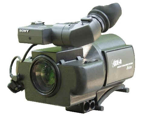
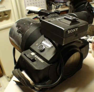
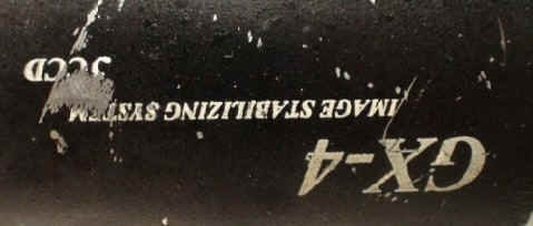
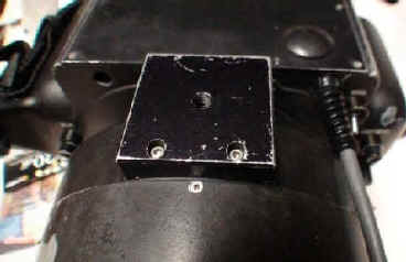
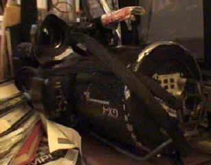
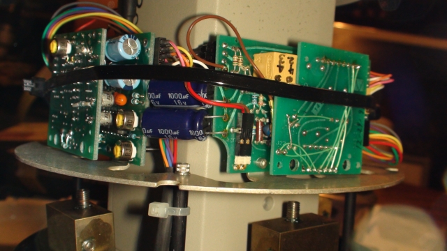
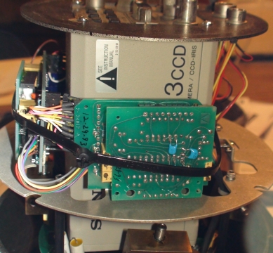
Above is a GX-4 although the museum's says GX-4 on the side of
the can,.... the label says GX-3.... is it a morph of the two
models?
label says gx-3 but can below says gx-4 but not the gx-4 I
see in the GX-4 photo at the top of this section.
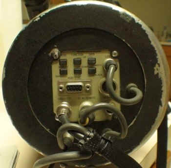
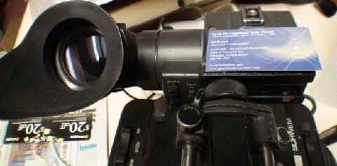
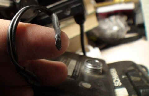
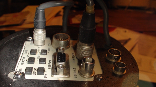
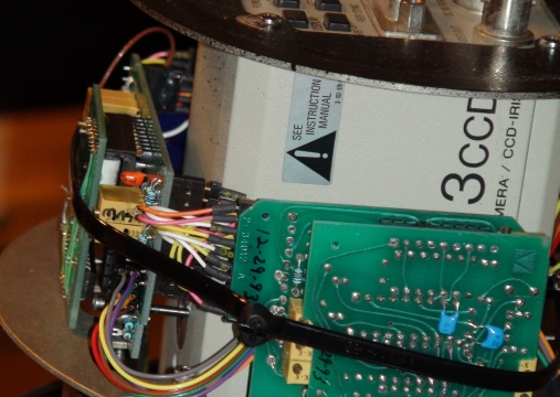
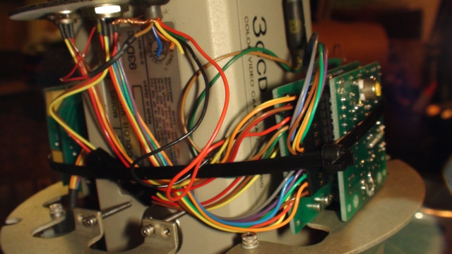
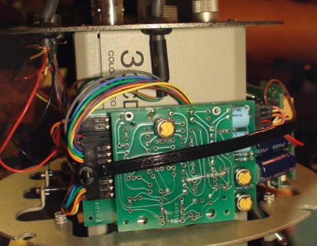
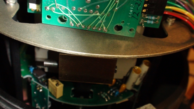
Sony M7 type viewfinder the DXF-M7
What the heck is this
loose wire? Well the camera works so we
will just tuck it under something...
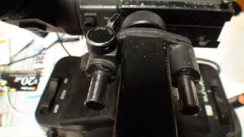
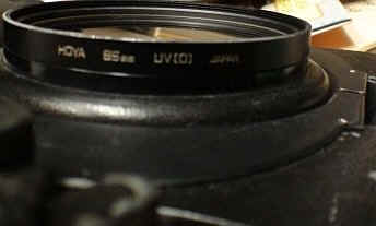
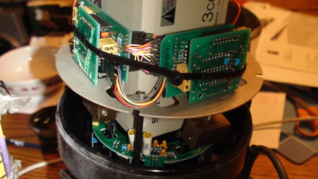
Anyone have an 85 mm mount wide-angle adapter I can stick on
this!?
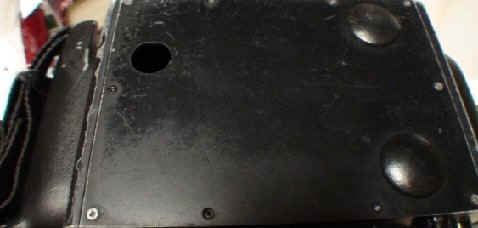
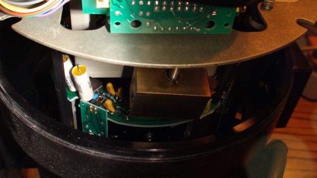
I dislike seeing open holes for dust to crawl into
need a plug like the other holes have!
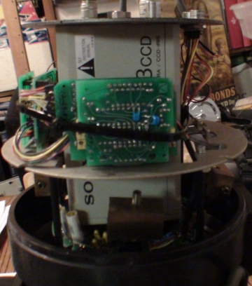
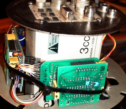
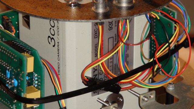
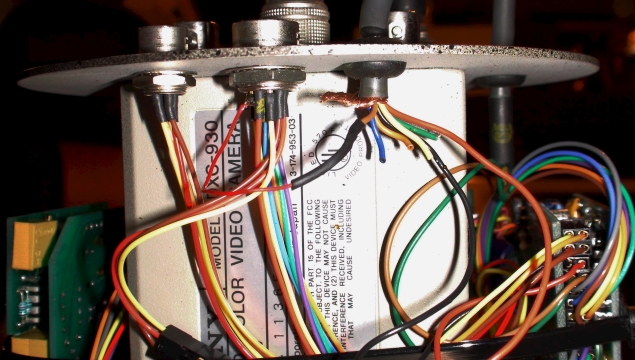
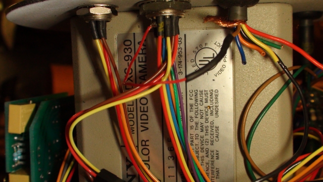
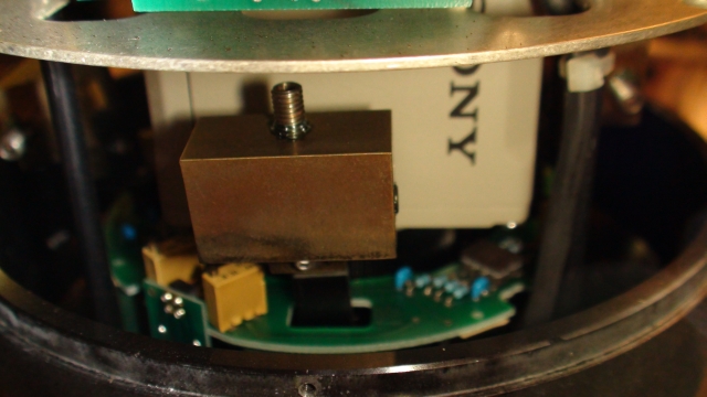
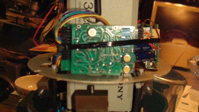
Inside the back can.... see the Sony DXC-930 camera.
If you have ever used any Schwem cameras or gyro lenses drop me a
note... we are interested in collecting up some interesting in the field
stories! Please email info@smecc.org
Schwem GX-4
Camera/Image Stabilizer
Stabilized video at high resolution
The new Schwem GX-4 from Tinsley Laboratories gives
you everything you need for shooting from moving
platforms - broadcast quality resolution, a great zoom lens,
and rock-solid image stabilization .
It matches the new Sony DXC-9503-CCD camera (over
700 lines of horizontal resolution) and a Fujinon 8X zoom
with Schwem's unique optical image stabilization. The
package weighs just 8.5 pounds. Fully configured for ENG
operation it’s still under 12 pounds.
The GX-4 is the perfect camera system for shooting fastbreaking
news from helicopters, airplanes, boats and motor
vehicles. Even hand held. It gives you stable video even when
the platform is moving or shaking. It frees you forever from
bulky, unwieldy, expensive mechanical stabilizers and
mounts..
GX-4 features
. Resolution of 720 Lines.
. Up to 98% effective stabilization
. 16 to 128 mm 8X zoom lens
. Compact, lightweight, well balanced
. Fast pan and tilt
. Optional remote control
. Computer designed optics
. Low power consumption
. Standard composite video out
Specifications:Stabilizer:
Stabilization 		1.0 Hz. - 87%
			4.0 Hz. - 96%
			10.0 Hz. - 98%
Stable Region 		+/- 2%
Angular Freedom 	+/- 5%
Limiting pan Rate 	> 50E/second
Camera (Sony DCX-950):
Imager 			3-CCD ½", interline transfer type
Horizontal Resolution 	720 H TV Lines
Sensitivity		2000 Lux (f 5.6, 3200K)
Signal to Noise Ratio 	58 dB
Gain Control 		Auto, manual 0 to 18 db in units of 1 dB
White Balance 		Auto, manual; Red and Blue Gain, Adjustable Individually
Electronic Shutter 	Speed Adjustable in Range 1/10,000 to 8.5 Seconds
Output Signals 		Composite: 1.0V p-p, 75 Ohms, RGB: 0.7V p-p, 75 Ohms
Zoom Lens (Fujinon A8x12RH):
Focal Length 		16 - 128mm
Zoom Ratio 		8x
Maximum Aperture 	f 2.8
Minimum Object Distance 1 meter
Angular Field of View 	39E 58" × 30E 30" to 5E 14" × 3E 56"
System:
Power Consumption 	< 12 watts
Power Supply 		12 - 15 VDC
Weight 			8.5 pounds, without handheld options
Remote Control Panel	(Optional) Includes Controls For Auto/Manual Iris, Focus, Zoom
Stabilizer 		On/Off
Hand Held Configuration (Optional) Includes Viewfinder, Handgrips, Servo Controls,
Stabilizer 		On/Off
Dimensions 		12" long x 4.5 - 6.5" high (without hand held options
Luis Alvarez explains in his Book "ALVAREZ"...
Our African trip resulted in the founding of a new
industry, stabilized optics. Jan recovered quickly. Back in Berkeley, Pete
Schwemin made a working model of the stabilized system I had designed, and we
showed it to Chuck Percy, the president then of Bell & Howell. Chuck liked
it and supported our Optical Research and Development Company (ORDCO) with a
research and development contract. We produced half a dozen different
stabilizing systems that Bell & Howell built into cameras and binoculars.
Chuck wanted to market them, but he also wanted to run for the Senate. He
succeeded, of course, and his successors, less venturesome, terminated our
support. Eventually the patent I assigned to them expired. In 1981 Pete and I
formed Schwem Technology. I am its chairman of the board and chief inventor.
Jan is its full-time president.
I spent almost a year at a computer terminal learning to
design highly corrected lens systems. That's a skill few physicists ever
learn. I took it on as a challenge and found it interesting. The most important
result of the exercise is that I can now communicate with our highly skilled
optical consultant, Dick Altman. Dick does all our final lens designs. Schwem
produces and sells stabilizing zoom lenses for the shoulder-mounted video
cameras used in electronic news gathering. The large inertial helicopter
mountings that serve for the production of television commercials are too
expensive for local television stations. Our lens, the Schwem Gyrozoom, which
works between 60 mm and 300 mm ("extreme telephoto"), is completely
portable and priced to make it affordable for every TV news truck. It doesn't
stabilize either the camera or the lens, but only the image being recorded.
Dave Packard liked our demonstration videotapes and became a substantial
Schwem investor.
I spoke with Dave's secretary, Margaret Paull, not long
ago. She asked me what I was doing. "Working on dinosaurs," I
replied, "and trying to make some money for Dave." "He doesn't
need any more," she said, a conclusion based on having to clean his
office of a torrent of begging mail after Fortune posted his picture on its
cover as the U.S. citizen whose net worth had increased the most in the
preceding ten months-about $1.2 billion. I've already told how Bill Hewlett
supported our pyramid project. Now his partner's name turns up. That's very
appropriate, since my introduction to business came in 1957 when Bill and Dave
invited me to sit on the small board of directors of the small Hewlett-Packard
company. I served in that capacity for a very interesting twenty-seven years
as the company grew into a $4-billion-a-year giant. One year recently HP and
IBM tied for first place in Fortune's annual poll to determine which U.S.
company American businessmen most admire. I reached the mandatory retirement
age in 1984 (sometimes referred to as "statutory senility"), but
at Bill's and Dave's request I continue to serve as a salaried consultant to
HP Labs. Jan and I made many trips to HP plants in Europe and in the Far East,
and we could have had no finer course in how to run a business than the one
Bill and Dave gave us from a front-row seat. We have started two different
optical companies in two quite different fields; without such fine tutors I
wouldn't have dreamed of going into business. The first of the two companies
was quite successful and was sold to a large pharmaceuticals company in 1979.
Hewlett-Packard and its people deserve more mention here than they've had,
which just shows that there are people in this world called editors.
The last paragraph speaks of two optical companies, but
I've mentioned only the one in the field of stabilized optics. The earlier one
exploited a very unusual type of lens I invented when I had to start wearing
bifocals and decided that there should be a better way to handle my
age-related inability to focus my eye lenses than the bifocals Ben Franklin
invented two centuries earlier. I came up with a completely new kind of lens
system in which the focusing was accomplished by moving two odd-shaped
plastic elements at right angles to the line of sight. Although no one has
yet marketed the system for its intended use in spectacles, our company,
Humphrey Instruments, sold optometric testing instruments that used our
"transverse optics," and the Polaroid Corporation introduced a new
camera in 1986 in which the focusing is accomplished by such transverse lens
motion.
We demonstrated the technology to Polaroid more than twenty
years ago, and had looked forward to receiving royalties for its use, but the
company avoided any royalty payments by waiting out the seventeen-year
lifetime of the patent. It expired two years ago, so anyone is now free to use
the invention. We sold Humphrey to Smith,
Kline several years ago-my first profit on any of my forty patents and Jan,
Pete, and I are back now as entrepreneurs, watching Schwem Technology move
toward profitability. Recently I heard Bob Wilson, who directed Fermilab for
many years, discuss the small company he's founded to sell superconducting
accelerators to hospitals for therapeutic use. "I've spent my whole
life in a socialistic society," Bob said, "getting money from
the government to do things with no commercial value. So I find it exciting to
enter the capitalistic world where your success is measured by the numbers on
your financial statements." I'm happy that I didn't have to leave the
world of science to dabble in the world of business. I agree with Bob that
business is exciting and challenging, and as a hobby it certainly beats
bridge.
274
Tinsley Laboratories seems to be
the owners of Schwem...... but I do not see any cameras listed
any more... Tinsley makes space telescope lenses and....
google them! There also may be a tie in with L-3
Communications.
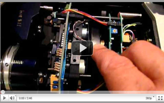
Watch This Video On the
Schwem Gyro Lens.
This is the add-on lens to be used with
an existing ENG camera.
Everyday we rescue items you
see on these pages!
What do you have hiding in a closet or garage?
What could you add to the museum displays or the library?